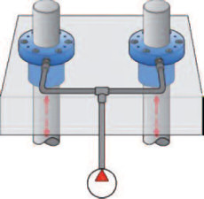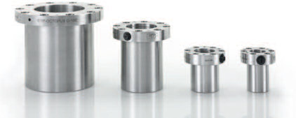
ETP-OCTOPUS is available as standard to suit shafts from 30mm to 100 mm. The number of mountings can be between 100 000 - 500 000 dependant on the clamping force (pressure) required. ETP-OCTOPUS is easy to build into applications, as no hub is required which allows for fast, frequent and accurate clamping and positioning. With the ability to have more than one ETP OCTOPUS operating intelligently and independently of each other via a hydraulic control system the product had many possibilities in today's automation of production lines.
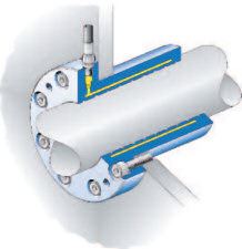
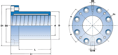
ETP-OCTOPUS is a hydraulic connection which consists of a quality double-walled hardened steel sleeve with a mounting flange. In the flange there are BCD mounting holes for ease of attachment. With the self contained unit there is also a shaft scraper, the threaded connection for hydraulic oil and an air relief screw. The inner diameter of the unit has spiral tracks in order to get an even friction and a defined locking force to the shaft.
The assembly of the hub is done with the screw joint. When hydraulically pressurised the inner sleeve expands uniformly against the shaft and creates a rigid joint. The sleeve does not expand to the outside. When the pressure is released the sleeve returns to its original size and can then easily be moved along the shaft to its new position and be re-pressurised.Customised designs are also available on request.

Pressure setting is done with an external pressure source. Several connections can be clamped/loosened simultaneously.

No hub is required for a design with ETP-OCTOPUS as the sleeve is thick enough to withstand the hydraulic pressure.

![]()

| ETP-OCTOPUS® | Dimensions | Transmittable torque or axial force | Screw joint for screw: DIN 912, 12.9 | Bore (4 pcs.) for scraper a° | Weight kg | ||||||||||
|---|---|---|---|---|---|---|---|---|---|---|---|---|---|---|---|
| d mm | D mm | D1 mm | L mm | L1 mm | T1 Nm | T2 Nm | FA1 kN | FA2 kN | n | D2 mm | Dim. | Tt Nm | |||
| 30 | 30 | 42 | 66 | 55 | 75 | 140 | 230 | 9 | 15 | 6 | 52 | M6 | 17 | 30 | 0,7 |
| 35 | 35 | 48 | 72 | 55 | 75 | 180 | 300 | 10 | 17 | 6 | 58 | M6 | 17 | 30 | 0,8 |
| 40 | 40 | 55 | 79 | 55 | 75 | 270 | 420* | 13 | 21 | 6 | 65 | M6 | 17 | 30 | 1,0 |
| 45 | 45 | 62 | 86 | 55 | 75 | 370 | 460* | 16 | 25 | 6 | 72 | M6 | 17 | 30 | 1,2 |
| 50 | 50 | 70 | 101 | 80 | 100 | 710 | 1000 | 28 | 42 | 8 | 84 | M8 | 40 | 45 | 2,0 |
| 60 | 60 | 83 | 114 | 100 | 120 | 1200 | 1500* | 42 | 62 | 8 | 97 | M8 | 40 | 45 | 3,0 |
| 70 | 70 | 97 | 128 | 120 | 140 | 1700* | 1700* | 64 | 92 | 8 | 111 | M8 | 40 | 45 | 4,6 |
| 80 | 80 | 110 | 148 | 130 | 150 | 3300 | 4000* | 84 | 110 | 10 | 128 | M10 | 79 | 54 | 6,2 |
| 90 | 90 | 125 | 163 | 130 | 150 | 4100 | 4400* | 91 | 130 | 10 | 143 | M10 | 79 | 54 | 8,0 |
| 100 | 100 | 138 | 176 | 130 | 150 | 4800* | 4800* | 105 | 140 | 10 | 156 | M10 | 79 | 54 | 9,5 |
| T1 resp. T2 = transmittable torque when axial force is 0. | } At pressure p1 (350 bar) resp. p2 (450 bar). | Dimensions subject to alterations without notice. | |||||||||||||
| FA1 resp. FA2 = transmittable axial force when torque is 0. | |||||||||||||||
| * For these torque values the screw joint sets the upper limit for the torque. Tt = recommended tightening torque for the screws. | |||||||||||||||
Shaft f7.
Hub H7 for clearance fit.
N7 for light press fit.
Can also be used without a hub.
Depends on the surrounding components within the system (connections/hoses).
All types of hydraulic oils can be used.
To prevent abnormal wear of the contact surfaces, the use of a scraper to clean the shaft is recommended. It can be mounted in a ring which is fastened with screws to the flange.
The number of cycles mainly depends on the pressure. The following guide values can be used:
p = 300 bar: 500 000 cycles.
p = 350 bar: 300 000 cycles.
p = 450 bar: 100 000 cycles.
More cycles may cause the sleeve to fatigue.
T and FA changes linearly between the given pressures for a certain shaft size. We do not recommend pressures above 450 bar.
The surfaces between ETP-OCTOPUS and the shaft should when moving, create a minimum amount of friction in order to avoid wear, but at the same time when clamping give enough holding force.
This will also be maintained if, as we recommend, the surfaces are reasonably lubricated with mineral oil. The spiral tracks inside the sleeve ensures that any unnecessary amount of lubricant is transferred away. Grease or Molybdendisulfide based lubricants should not be used.
For models which clamp only to the outside or in both directions there are possible solutions. For such cases please send us information and we will then send a suggestion/quotation.
