
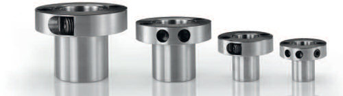
ETP-POWER is available as standard for shafts 15 – 40 mm. Run out ≤ 0,03 mm. Number of mountings 200 - 500 (size dependent).
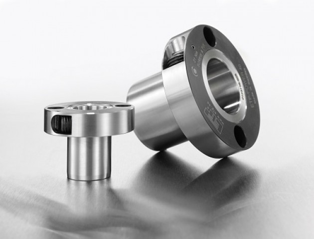
ETP-POWER combines quick mounting with a high radial load capacity due to the specially developed pressure medium. As the name suggests, ETP POWER is for higher torque applications.
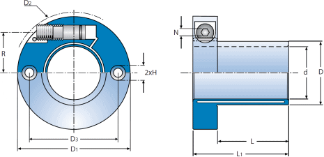
ETP-POWER is a hydraulic connection which consists of a double-walled hardened steel sleeve filled with a specially developed pressure medium and a flange. The flange part contains screw and piston with seals to maintain pressure. In the flange there are two pre-machined bores which can be used for mounting location pins, screws to the hub or similar.
When the pressure screw is tightened the double-walled sleeve expands uniformly against shaft and hub and creates a rigid joint. Dismantling is done by loosening the screw. ETP-POWER returns to its original dimensions and can easily be dismantled.
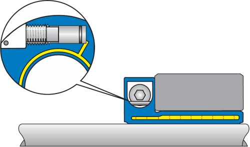
When the pressure screw is tightened to the recommended tightening torque, the piston has reached the bottom of the bore. ETP-POWER has created a uniform surface pressure against the shaft and hub.
![]()
Shaft k6-h7 for d = 19, 22, 24, 28, 32, 38 mm.
Shaft h8 for all other dimensions d.
Hub H7.
Transmittable torque, T, is for static load. If the load is alternating or pulsating torque, reduce the transmittable torque, T, with the following factors: (factor x T).
Alternating: 0,5 x T.
Pulsating: 0,6 x T.
