
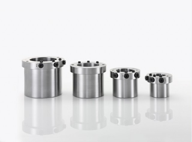
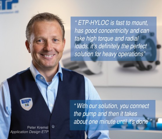
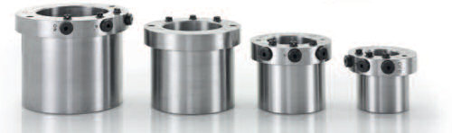
One of the most innovative ways of reliably clamping hubs and shafts, whilst delivering high torque and maintaining excellent concentricity. ETP-HYLOC is available as standard to suit shaft sizes between 50mm and 220 mm. Concentric run out can be as little ≤ 0,02 mm. With the Hyloc series the number of mountings can be a maximum of 2000 times making it particularly suited to applications where hub and shafts require frequent clamping and finite adjustment. The robust design, makes the product ideally suited to more arduous environments and heavy operations like steel rolling mills and the processing industry.
Full customisation of the standard product is available as well as models for shaft greater than 220 mm can also be offered on request. For extreme high torque applications the contact surfaces of ETP-HYLOC (sizes ≥100 mm) can be applied with ETP-HFC, a high friction coating, which doubles the torque capacity.
This product is a solution looking for a challenge.
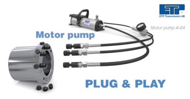
When the internal piston is moved, by the hydraulic pressure from the pump, the double-walled sleeve expands uniformly against shaft and hub to form a rigid joint. When dismantling, the piston is moved in the opposite direction and the joint will loosen. A small amount of oil will be taken via spiral tracks in the piston between the surfaces (pressure applied through the "P" connection), in this way making it easier for the piston to move. Normal working pressure is 1000 bar.
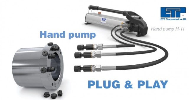
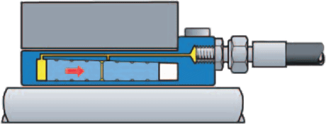
Mounting: apply pressure in the "ON" and "P" (not shown) connections.When mounted no hydraulic pressure remains. The small conical angle prevents the piston from releasing.
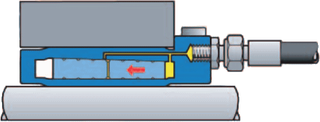
Dismantling: apply pressure in the "OFF" and "P" (not shown) connections. ETP-HYLOC returns to its original measurements and the joint is loose.
![]()
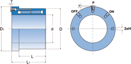
Shaft h7 for h8
Hub H7.
The contact surfaces L and L1 must be completely covered by the shaft and hub. The oil for the pump should be a transmission oil type 80 W. For other hub materials, for example aluminium, contact us.
The mounting pressure is normally 1000 bar. Max mounting pressure 1200 bar. Dismantling requires approx. 200 bar higher pressure than for mounting.
ETP-HYLOC can be designed to suit special applications on request, and also larger sizes are available.
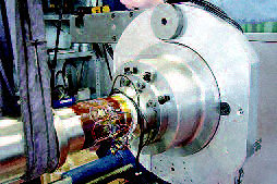
 Good runout, easy to position
In this straightening line for steel, the forming rollers are fastened with ETP-HYLOC. The position of the rollers relatively to each other along the shafts are exactly adjusted, it will not change during pressurising. The radial runout is minimised and the change of rollers facilitated. High radial forces can be transmitted with ETP-HYLOC, as the connection is solid all through.
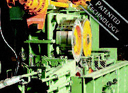
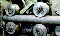 Good runout, simple to adjust
ETP-HYLOC, due to its robust design, is suited for difficult environments and heavy operations. Here the feed rollers are fastened in a steel mill. Adjustment of the rollers is easy to do and with high precision. When in operation the good runout is important. When the rollers need to be changed the quick dismantling is valuable to decrease down time.
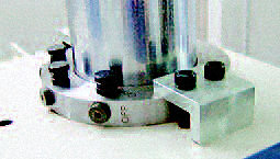
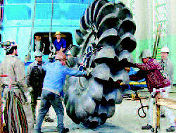 Good runout, thin hub
Fastening and centering of a turbine runner puts high requirements on the connection. Often a relatively soft material is used in the hub, which should be subject to a limited tension. The moderate and even surface pressure from ETP-HYLOC works well also with thin walled hubs. The high speeds require good runout. Mounting and adjusting is made easy and fast due to the easy pressure setting.
 Precision fastening, quick adjustment
Fastening of the measuring shaft and the part which will be subject to a torque, in this torque test rig in the automobile industry, are both done with ETP-HYLOC. Precision, no backlash, limited surface pressure that does not damage the surfaces and quick change of parts to be tested are important factors.
 High axial forces, simple adjustment
Four chop and trimming shears in this machine, which belongs to a processing line for steel, must be accurately synchronised. On each wheel there are a number of knives, which trim front and back end coils which passes through. ETP-HYLOC centres and fastens the wheels. The knives are synchronised along and around the shafts and maintain their accurate positions during pressurising. The uneven dynamic loads in the radial direction are transferred through ETP-HYLOC.
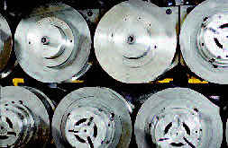
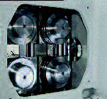
 Accurate positioning, dynamic loads
Four chop and trimming shears in this machine, which belongs to a processing line for steel, must be accurately synchronised. On each wheel there are a number of knives, which trim front and back end coils which passes through. ETP-HYLOC centres and fastens the wheels. The knives are synchronised along and around the shafts and maintain their accurate positions during pressurising. The uneven dynamic loads in the radial direction are transferred through ETP-HYLOC.
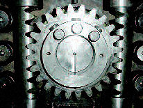 High torque,
The gear for operating a machine for production of pet food is fastened with ETP-HYLOC. Important at the selection was the accurate adjustment to avoid backlash, the possibility to take up high peak loads at emergency stops, as well as the easy and quick mounting.
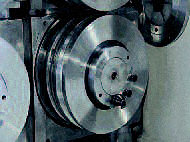 High radial force, quick changes
Centering and fastening of the feed rollers in a processing line for steel working. ETP-HYLOC centres the rollers, take up and transfers the high and irregular radial forces to the shaft. Adjustments to change worn out rollers and change to other profiles are done with a minimum of downtime, with the help of only a hydraulic handpump.
