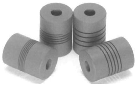
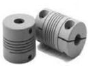
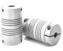
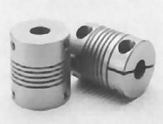
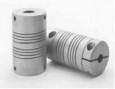
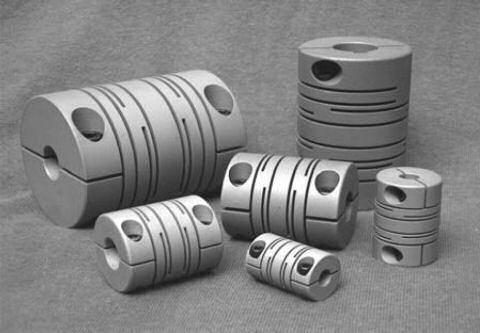
A single piece construction, zero backlash, constant velocity shaft coupling that simultaneously compensates for angular, parallel and skewed shaft misalignments.
Available in Stainless Steel or Aluminium as standard with both metric and imperial bores sizes stocked ready to be delivered.
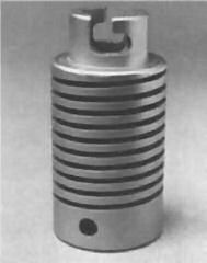
By varying the thickness of the coils, a Flexure can accommodate increasing amounts of torque and radial loads. The designer may specify torsional stiffness and compression spring rates independent of other factors.
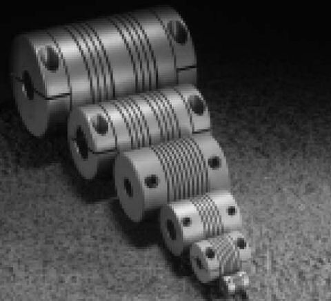
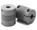
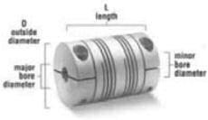
The individual performance capability of each Flexure is detemined by: coil width, inside diameter, number of coils, number of starts and material. Altering any one of these factors changes the performance characteristics of the “Flexure”. For example, the helical flexures illustrated display identical outside diameters and lengths. The effects of their variable characteristics - such as coil width, inside diameter, number of coils and starts are explained in the adjacent pictures.
As the coil width or inside diameter are changed such aspects as torque...angular misalignment (bending moment)...parallel offset (radial load)... torsional stiffness... and compression spring rate, are altered.
As the number of coils is changed, all of the characteristics except the torque capacity are affected.
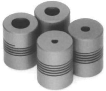
When the inside diameter changes, so does the torque capacity, torsional stiffness and axial spring rates.
The proper material used in the manufacture of any helical flexure affects much more than just torque capacity. Factors such as elasticity, fatigue, corrosion resistance, mass, magnetic permeability, operating temperature, availability and cost also play important roles. High strength materials such as 17- 4PH CRES*, 15-5PH, C300, BETA C Titanium and 7075-T6 Aluminium, are just a few of the common choices for meeting design and performance needs.
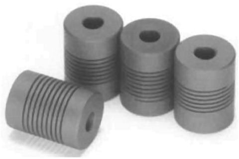
When the number of coils is changed the torque capability remains unaffected. All of the other characteristics change.
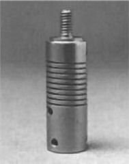
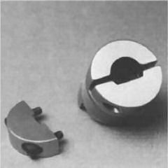
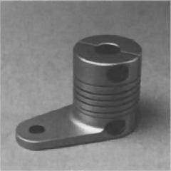
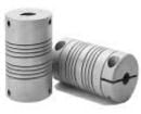
In addition to being able to alter the characteristics of the flexure, you may have your attachment method integrated into the final product.
Typical attachment options might include:
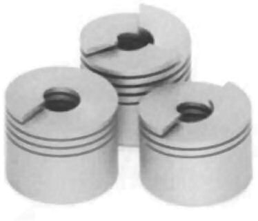
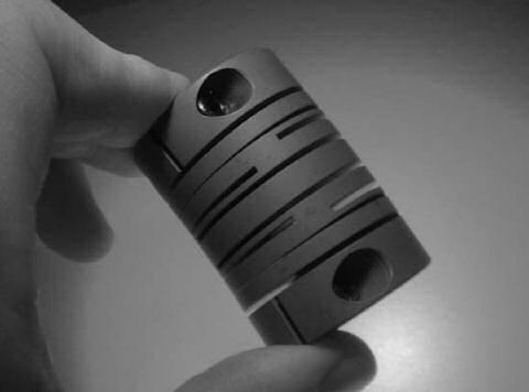
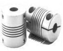
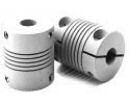
Multiple, (typically two) helical beams provide high torsional stiffness. Shown: single, double and triple start.
Flexures may be engineered to include a variety of bore configurations. These variations include round, threaded, single or double-D, spline, keyway, tapered or ... your choice!
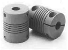
The flexible coil section of the coupling can be custom designed and manufactured to your specifications. Whether your considerations include high torque, angular or parallel misalignment, critical torsional stiffness, precise compression spring rates, or special end connections, chances are excellent that the flexure will meet or exceed your particular design requirements.
The flexure concept brings enormous design flexibility to your applications. Depending on your needs, the flexure can serve as a flexible shaft coupling, universal joint, machined spring or your own specialised component.
The flexure's ability to accommodate various performance characteristics and its ability to integrate attachments directly enhances your freedom to design.
Not only does the flexure integrate multiple functions and parts into a single compact unit - no moving parts, no maintenance and no backlash - it can incorporate complex attachments.
High quality performance is achieved with magnetic or non-magnetic corrosion-resistant stainless steel, as well as aluminium alloys. Flexures are also successfully manufactured using various materials such as Delrin™ and titanium.
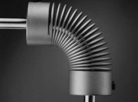
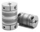
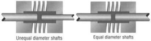
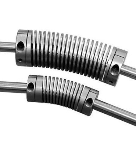
The flexing capactiy of the flexure can compensate for a variety of misalignments, including parallel, angular and skewed (three-dimensional misalignment. The Flexure solutions for these misalignment situations are shown in the adjacent photographs.

Angular misalignment is the easiest form of misalignment for most couplings to accept, and thus one of the most practical applications of a flexible coupling. Allowing only enough space between coils to partially close the gap during bending, the flexure can accept an angular misalignment of 20 degrees or more (and even up to 90 degrees in special ujoint applications).
The basic requirement of a flexible coupling is to transmit torque loads without permanent distortion or damage and without imposing undue bending or radial load ,upon the driver or driven components. Once the working torque rating of a flexure coupling is established - based on misalignment and design criteria, material specifications and service factors supplied during the design process - its operational life is virtually unlimited.
Every flexible shaft coupling has some torsional flexibility. Torsional flexibility reflects the amount of twist in a system; torsional stiffness the degrees of resistance against twist. The flexure can be configured (with thicker coils, for example), to provide the exact amount of torsional flexibility required in an application.
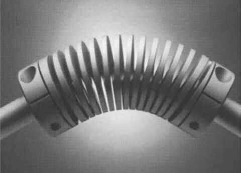
Parallel misalignment is the most difficult form of misalignment for couplings to compensate for. It can also be the most damaging to shafts, bearings and motors. The flexure, through lateral displacement, transforms an application's parallel misalignment problems into angular displacement within the coupling. The centre coils of the flexure can become an intermediate shaft that can allow 10, 20 or 30 thousandths of an inch of parallel offset or more.

When shafts are not in the same plane (skewed), the flexure's abilities to compensate are the same as with either parallel or angular misalignment - but in the third dimension. A flexure designed with more coils in a series can compensate for as much three dimensional misalignment as your applications requires.
Bearing loads are primarily generated by a couplings natural resistance to bending, and can be very destructive forces to an apparatus and its rotational components. The flexure maintains a very constant radial and bending load at all points of rotation, providing exceptionally uniform bearing loads.
In a rotating system, constact velocity refers to the relative rotational speed of the input and output shafts. In a constant velocity system the driven end of the coupling turns exactly the same rate as the driver end. When operating under a uniform load the flexure design provides constant velocity and alleviates:
| A Series | H Series | DS Series | MCA Series | MC7 Series | W Series | W Series |
|---|---|---|---|---|---|---|
| Aluminium 7075-T6 | Stainless Steel 17-4PH | Aluminium 7075-T6 | Aluminium 7075-T6 | Stainless Steel 17-4PH | Aluminium 7075-T6 | Stainless Steel 17-4PH |
 |  |  |  |  |  |  |
| Description | ||||||
| General purpose, light to medium duty. An economical, maintenance free coupling, used in a variety of applications. Helical”s most popular coupling/coupler | Stainless steel version of “A” series, with higher torque capacity and torsional stiffness. Increased fatigue resistance. | Low inertia, high performance, aluminium coupling, using Helical double start technology. Torsionally stiffer and higher torque capacity than the “A” series. Lighter with lower inertia than the “H” series. | A general purpose aluminium coupling, used where more parallel misalignment is required. Has a large range of shaft sizes, with optional keyways | Stainless steel version of “MCA(C)” series, with higher torque capacity and torsional stiffness. Increased fatigue resistance. | Metric dimensioned coupling, with metric fasteners. A light to medium duty coupling for those preferring to work strictly in the metric system. A general purpose coupling. | Stainless steel version of the “WA(C)” series, with higher torque capacity and torsional stiffness. Increased fatigue resistance with all metric dimensions and fasteners. |
| Typical Applications | ||||||
| Used for encoder/resolver applications, low torque pump, lead screw and various other applications. | For situations requiring a heavy duty coupling such as pumps, lead screws, and positioning systems; also for process equipment in industrial situations. Anywhere a rugged, tough, long-lasting coupling is needed. | For high speed motion control systems, where fast response time is important. E.g., lead and ball screws, encoders/resolvers, and anywhere high torsional stiffness is required. | Good for encoder/resolver applications, moderate torque pump, lead screw, and various other applications. | Good for pump, conveyor systems, and industrial processing equipment, where absolute reliability is required. Anywhere a rugged, tough, long-lasting coupling is needed. | Used for encoder/resolver applications, low torque pump, lead screw and various other applications. | For situations requiring a heavy duty coupling for pump, lead screws, and positioning systems; also for process equipment in industrial situations. Anywhere a rugged, tough, long-lasting coupling is needed. |
| Misalignment Compensation | ||||||
| 5° angular, .010 inch parallel offset, .010 inch axial motion | 5° angular, .010 inch parallel offset, .010 inch axial motion | 3° angular, .010 inch parallel offset, .008 inch axial motion | 5° angular, .030 inch parallel offset, .010 inch axial motion | 5° angular, .030 inch parallel offset, .010 inch axial motion | 5° angular, .25mm parallel offset, 25mm axial motion | 5° angular, .25mm parallel offset, 25mm axial motion |
| Torque Range | ||||||
| 1.2-51 lbin | 2.4-100 lbin | 12-234 lbin | 20-286 lbin | 40-556 lbin | 59-20 Nm | 1.2-39 Nm |
| Standard Bores (inch and or metric bores available in all couplings) | ||||||
| 0.059-0.750 inch 1.5-19.05mm | 0.059-0.750 inch 1.5-19.05mm | 0.188-0.750 inch 4.78-19.05mm | 0.250-.875 inch 6.35-22.23mm | 0.250-1.000 inch 6.35-25.40mm | 3mm-38.1mm | 3mm-38.1mm |
| Attachment | ||||||
| Clamp or set screw | Clamp or set screw | Clamp | Clamp or set screw Keyways optional | Clamp or set screw Keyways optional | Clamp or set screw | Clamp or set screw |
| Operating Temperatures | ||||||
| Up to 200°F | Up to 600°F | Up to 200°F | Up to 200°F | Up to 600°F | Up to 100°F | Up to 300°F |
| Speed (in the wind up direction) | ||||||
| 10,000 rpm | 10,000 rpm | 10,000 rpm | 3,600 rpm | 3,600 rpm | 10,000 rpm | 10,000 rpm |
The W Series can be used in a wide range of applications from driving components with light torque requirements, such as encoders and tachometers (aluminium), to lead screws and pumps requiring greater torque (stainless steel).
INTEGRAL CLAMP/WAC & W7C

SET SCREW/WA & W7 (TWO EACH END @ 120°)
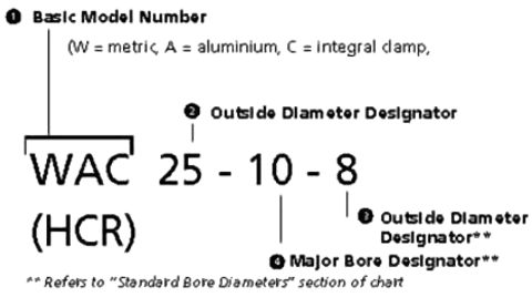
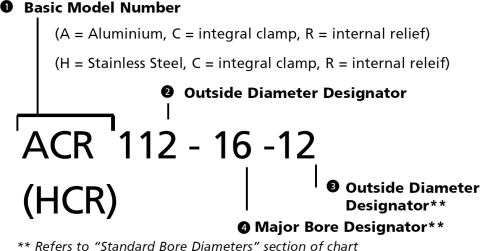
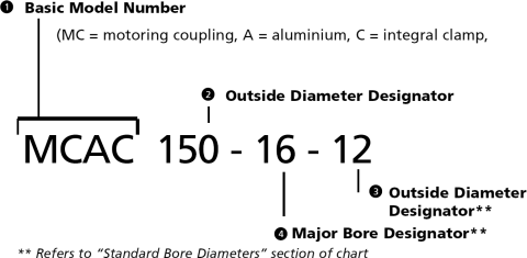
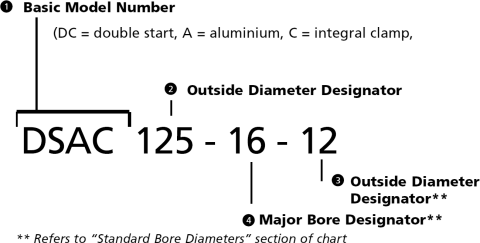
Coupling part numbers consist of four sections. To determine the correct numbers/letters for each section of a specific coupling part number, please refer to the charts on the following pages.
Example
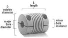
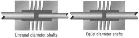
Internal Configuration - Relief*
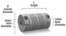
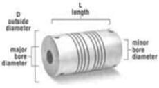
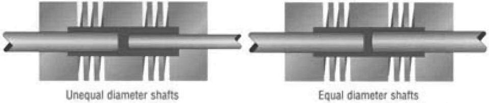
Major and minor diameter shafts may enter flexture area during operation.
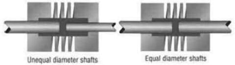
* Dark area indicates relief within the coupling interior
W7C = Stainless Steel, Integral Clamp
W7 = Stainless Steel, Set Screw
| Attachment Screw | |||||||||||||
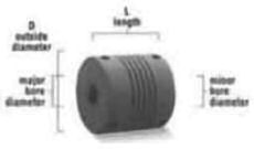
| Basic Model No. | Dimensional Information | Standard Bore Diameters | Performance Data | Inertia | Screw Size | Seating Torque | Centre Line | ||||||
|---|---|---|---|---|---|---|---|---|---|---|---|---|---|
| Integral Clamp Attachment | Set Screw Attachment | Outside diameter Designator | D Outside Diameter | L Length mm | (+0.05mm/-0.00mm) Note 5 | Momentary Dynamic Torque Note 2 (Nm) | Torsional Rate (degree/Nm) | x 10-4 (Kgcmsec2) Note 6 | Integral Clamp | Set Screw | (Nm) | (mm) | |
| Size mm | Bore Designator | ||||||||||||
| WAC | 15 | 15mm | 22 | 3.00 4.00 5.00 | 3mm 4mm 5mm | 0.71 0.66 0.59 | 5.1 7.2 10.0 | 0.028 | M2x.4 | 0.5 | 2.5 | ||
| WA | 20 | 0.025 | M3x.5 | 1 | 2.5 | ||||||||
| WAC | 20 | 20mm | 28 | 4.00 5.00 6.00 | 4mm 5mm 6mm | 1.3 1.2 1.1 | 2.7 3.5 4.5 | 0.11 | M3x.5 | 2 | 3.8 | ||
| WA | 20 | 0.079 | M3x.5 | 1 | 2.5 | ||||||||
| WAC | 25 | 25mm | 30 | 6.00 7.00 8.00 9.00 10.00 | 6mm 7mm 8mm 9mm 10mm | 2.9 2.8 2.6 2.4 2.2 | 1.5 1.8 2.2 2.8 3.5 | 0.30 | M3x.5 | 2 | 3.8 | ||
| WA | 24 | 0.24 | M4x.7 | 2.1 | 3 | ||||||||
| WAC | 30 | 30mm | 38 | 9.00 10.00 11.00 12.00 | 9mm 10mm 11mm 12mm | 4.9 4.6 4.3 4.0 | 1.1 1.3 1.6 1.9 | 0.78 | M4x.7 | 4.7 | 5 | ||
| WA | 30 | 0.60 | M5x.8 | 4.7 | 3.5 | ||||||||
| WAC | 40 | 40mm | 50 | 12.00 13.00 14.00 15.00 16.00 | 12mm 13mm 14mm 15mm 16mm | 12 11 11 10 9.7 | 0.45 0.51 0.59 0.67 0.78 | 3.3 | M5x.8 | 9.5 | 5.8 | ||
| WA | 50 | 3.3 | M6x1 | 7.7 | 6.7 | ||||||||
| WAC | 50 | 50mm | 54 | 14.00 16.00 18.00 19.00 20.00 | 14mm 16mm 18mm 19mm 20mm | 19 18 17 16 15 | 0.25 0.31 0.39 0.43 0.49 | 7.6 | M6x1 | 16 | 6.7 | ||
| WA | 54 | 7.6 | M6x1 | 7.7 | 7.5 | ||||||||
| * Refer to note 8 | |||||||||||||
| Basic Model No. | Dimensional Information | Standard Bore Diameters | Performance Data | Inertia | Screw Size | Seating Torque | Centre Line | ||||||
|---|---|---|---|---|---|---|---|---|---|---|---|---|---|
| Integral Clamp Attachment | Set Screw Attachment | Outside diameter Designator | D Outside Diameter | L Length mm | (+0.05mm/-0.00mm) Note 5 | Momentary Dynamic Torque Note 2 (Nm) | Torsional Rate (degree/Nm) | x 10-4 (Kgcmsec2) Note 6 | Integral Clamp | Set Screw | (Nm) | (mm) | |
| Size mm | Bore Designator | ||||||||||||
| W7C | 15 | 15mm | 22 | 3.00 4.00 5.00 | 3mm 4mm 5mm | 1.4 1.3 1.2 | 1.9 2.6 3.7 | 0.078 | M2x.4 | 0.5 | 2.5 | ||
| W7 | 20 | 0.07 | M3x.5 | 1 | 2.5 | ||||||||
| W7C | 20 | 20mm | 28 | 4.00 5.00 6.00 | 4mm 5mm 6mm | 2.6 2.5 2.3 | 1.9 2.6 3.7 | 0.32 | M3x.5 | 2 | 3.8 | ||
| W7 | 20 | 0.22 | M3x.5 | 1 | 2.5 | ||||||||
| W7C | 25 | 25mm | 30 | 6.00 7.00 8.00 9.00 10.00 | 6mm 7mm 8mm 9mm 10mm | 5.7 5.5 5.1 4.7 4.3 | 0.54 0.66 0.82 1.0 1.3 | 0.84 | M3x.5 | 2 | 3.8 | ||
| W7 | 24 | 0.66 | M4x.7 | 2.1 | 3 | ||||||||
| W7C | 30 | 30mm | 38 | 9.00 10.00 11.00 12.00 | 9mm 10mm 11mm 12mm | 9.5 8.9 8.3 7.7 | 0.40 0.48 0.58 0.70 | 2.2 | M4x.7 | 4.7 | 5 | ||
| W7 | 30 | 1.7 | M5x.8 | 4.7 | 3.5 | ||||||||
| W7C | 40 | 40mm | 50 | 12.00 13.00 14.00 15.00 16.00 | 12mm 13mm 14mm 15mm 16mm | 23 22 21 20 19 | 0.16 0.19 0.21 0.24 0.28 | 9.2 | M5x.8 | 9.5 | 5.8 | ||
| W7 | 50 | 9.2 | M6x1 | 7.7 | 6.7 | ||||||||
| W7C | 50 | 50mm | 54 | 14.00 16.00 18.00 19.00 20.00 | 14mm 16mm 18mm 19mm 20mm | 37 35 33 31 30 | 0.092 0.11 0.14 0.16 0.18 | 21 | M6x1 | 16 | 6.7 | ||
| W7 | 54 | 21 | M6x1 | 7.7 | 7.5 | ||||||||
| * Refer to note 8 | |||||||||||||
H Series
The A Series coupling meets performance demands over a wide range of applications, including drive systems for encoders, instrumentation, lead screws, small pumps, feed rollers and anywhere a light to medium duty, torsionally flexible coupling is required. High strength, excellent fatique resitance and high torsional stiffness is called for in your application. The H Series, premium performance capability is designed for applications requiring a heavy-duty coupling, such as drive systems, small pumps and gear boxes.
Integral Clamp / ACR & HCR
An array of options, in a variety of diameter sizes, allows you to tailor the A or H Series to your specific applications. A and H Series options include set screw or integral clamp attachments and inch or metric bores.
INTEGRAL CLAMP/ACR & HCR
SET SCREW/AR & HR (two each end @ 120°)
Coupling part numbers consist of four sections.
To determine the correct numbers/letters for each section of a specific coupling part number, please refer to the charts on the following pages.
Example
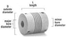
Internal Configuration - Relief*
Major and minor diameter shafts may enter flexure area during operation.

*Dark area indicates relief within the coupling interior
HCR = Stainless Steel, Integral Clamp
HR = Stainless Steel, Set Screw
| Attachment Screw | |||||||||||||
| Basic Model No. | Dimensional Information | Standard Bore Diameters | Performance Data | Inertia | Screw Size | Seating Torque | Centre Line | ||||||
|---|---|---|---|---|---|---|---|---|---|---|---|---|---|
| Integral Clamp Attachment | Set Screw Attachment | Outside diameter Designator | D Outside Diameter in. (mm) | L Length in. (mm) | (+.002in/-.000in) Note 6 | Momentary Dynamic Torque Note 2 (lbin) | Torsional Rate (degree/lbin) | x 105 (lbinsec2) Note 7 | Integral Clamp Note 4 | Set Screw Note 4 | (lbin) | (in.) | |
| Size in. (mm) | Bore Designator (1/32 in.) | ||||||||||||
| ACR | 050 | 1/2 (12.7) | 0.75 (19.05) | 0.094 (2.39) 0.125 (3.18) | 3 4 | 3.7 3.5 | 0.98 1.3 | 0.11 | 1-72 | 4 | .09 | ||
| AR | 0.50 (12.7) | 0.069 | 2-56 | 1.3 | .06 | ||||||||
| ACR | 062 | 5/8 (15.88) | 0.80 (20.40) | 0.125 (3.18) 0.157 (3.99) 0.188 (4.78) | 4 5 6 | 7.1 6.7 6.2 | 0.51 0.66 0.86 | 0.28 | 2-56 | 4.5 | .1 | ||
| AR | 0.62 (15.75) | 0.21 | 4-40 | 4.3 | .07 | ||||||||
| ACR | 075 | 3/4 (19.05) | 0.90 (22.75) | 0.125 (3.18) 0.157 (3.99) 0.188 (4.78) 0.250 (6.35) | 4 5 6 8 | 10 10 9.8 8.6 | 0.29 0.36 0.44 0.68 | 0.66 | 4-40 | 10 | .12 | ||
| AR | 0.75 (19.05) | 0.54 | 6-32 | 8 | .09 | ||||||||
| ACR | 087 | 7/8 (22.22) | 1.06 (26.98) | 0.188 (4.78) 0.250 (6.35) 0.313 (7.95) | 6 8 10* | 19 17 15 | 0.20 0.28 0.41 | 1.5 | 6-32 | 19 | .15 | ||
| AR | 0.87 (22.22) | 1.2 | 6-32 | 8 | .1 | ||||||||
| ACR | 100 | 1 (25.4) | 1.25 (31.75) | 0.250 (6.35) 0.313 (7.95) 0.375 (9.53) | 8 10 12 | 27 24 22 | 0.17 0.24 0.33 | 3 | 6-32 | 19 | .15 | ||
| AR | 1.00 (25.4) | 2.3 | 10-24 | 25 | .15 | ||||||||
| ACR | 112 | 1 1/8 (28.75) | 1.50 (38.1) | 0.250 (6.35) 0.313 (7.95) 0.375 (9.53) 0.500 (12.70) | 8 10 12 16 | 43 40 37 28 | 0.094 0.12 0.17 0.32 | 5.6 | 6-32 | 19 | .15 | ||
| AR | 1.12 (28.5) | 4.1 | 10-24 | 25 | .14 | ||||||||
| ACR | 125 | 1 1/4 (31.75) | 1.62 (41.27) | 0.375 (9.53) 0.500 (12.70) 0.625 (15.88) | 12 16* 20* | 48 39 29 | 0.11 0.20 0.37 | 9.3 | 10-24 | 50 | .22 | ||
| AR | 1.25 (31.75) | 6.9 | ¼-20 | 65 | .16 | ||||||||
| * Refer to note 8 | |||||||||||||
| Attachment Screw | |||||||||||||
| Basic Model No. | Dimensional Information | Standard Bore Diameters | Performance Data | Inertia | Screw Size | Seating Torque | Centre Line | ||||||
|---|---|---|---|---|---|---|---|---|---|---|---|---|---|
| Integral Clamp Attachment | Set Screw Attachment | Outside diameter Designator | D Outside Diameter in. (mm) | L Length in. (mm) | (+.002in/-.000in) Note 6 | Momentary Dynamic Torque Note 2 (lbin) | Torsional Rate (degree/lbin) | x 105 (lbinsec2) Note 7 | Integral Clamp Note 4 | Set Screw Note 4 | (lbin) | (in.) | |
| Size in. (mm) | Bore Designator (1/32 in.) | ||||||||||||
| HCR | 50 | 1/2 (12.7) | 075 (19.05) | 0.094 (2.39) 0.125 (3.18) | 3 4 | 7.5 7.0 | 0.36 0.48 | 0.31 | 1-72 | 4 | .09 | ||
| HR | 0.50 (12.7) | 0.19 | 2-56 | 1.3 | .06 | ||||||||
| HCR | 62 | 5/8 (15.88 ) | 0.80 (20.40) | 0.125 (3.18) 0.157 (3.99) 0.188 (4.78) | 4 5 6 | 14 13 12 | 0.19 0.24 0.31 | 0.78 | 2-56 | 4.5 | .10 | ||
| HR | 0.62 (15.75) | 0.58 | 4-40 | 4.3 | .07 | ||||||||
| HCR | 75 | 3/4 (19.05 ) | 0.90 (22.75) | 0.125 (3.18) 0.157 (3.99) 0.188 (4.78) 0.250 (6.35) | 4 5 6 8 | 21 20 20 17 | 0.11 0.13 0.16 0.25 | 1.8 | 4-40 | 10 | .12 | ||
| HR | .75 (19.05) | 1.5 | 6-32 | 8 | .09 | ||||||||
| HCR | 87 | 7/8 (22.22 ) | 1.06 (26.98) | 0.188 (4.78) 0.250 (6.35) 0.313 (7.95) | 6 8 10* | 37 34 30 | 0.072 0.10 0.15 | 4.1 | 6-32 | 19 | .15 | ||
| HR | 0.87 (22.22) | 3.3 | 6-32 | 8 | .10 | ||||||||
| HCR | 100 | 1 (25.4) | 1.25 (31.75) | 0.250 (6.35) 0.313 (7.95) 0.375 (9.53) | 8 10 12 | 52 47 42 | 0.062 0.86 0.12 | 8.3 | 6-32 | 19 | .15 | ||
| HR | 1.00 (25.4) | 6.5 | 10-32 | 25 | .15 | ||||||||
| HCR | 112 | 1 1/8 (28.75 ) | 1.50 (38.1) | 0.250 (6.35) 0.313 (7.95) 0.375 (9.53) 0.500 (12.70) | 8 10 12 16 | 83 78 71 55 | 0.035 0.045 0.061 0.12 | 15.6 | 6-32 | 19 | .15 | ||
| HR | 1.12 (28.5) | 11.3 | 10-32 | 25 | .14 | ||||||||
| HCR | 125 | 1 1/4 (31.75 ) | 1.62 (41.27) | 0.375 (9.53) 0.500 (12.70) 0.625 (15.88) | 12 16* 20* | 95 77 57 | 0.041 0.071 0.13 | 26 | 10-32 | 50 | .22 | ||
| HR | 1.25 (31.75) | 19.4 | ¼-28 | 65 | .16 | ||||||||
| * Refer to note 8 | |||||||||||||

This versatile series of couplings provides you with a full range of torque capacities and bore sizes, with 1/32-inch parallel misalignment capability. These couplings attach to shafts with your choice integral clamps or set screws. Combine this with optional keyways and the MC Series is tailor-made your application.
From medium-duty (aluminium) to heavy-duty (stainless steel), this series provides for a wide range applications. From pumps and lead screws to conveyors, chances are an MC Series coupling will your needs. Available in 7075-T6 aluminium alloy or 17-4 PH corrosion resistant steel (CRES).
INTEGRAL CLAMP/MCAC & MC7C
SET SCREW/MCA & MC7 (two each end @ 120°)
Coupling part numbers consist of four sections.
To determine the correct numbers/letters for each section of a specific coupling part number, please refer to the charts on the following pages.
Example
Internal Configuration - Relief*
Major and minor diameter shafts may enter
flexure area during operation.
*Dark area indicates relief within the coupling interior
MC7C = Stainless Steel, Integral Clamp
MC7 = Stainless Steel, Set Screw
| Attachment Screw | |||||||||||||
| Basic Model No. | Dimensional Information | Standard Bore Diameters | Performance Data | Inertia | Screw Size | Seating Torque | Centre Line | ||||||
|---|---|---|---|---|---|---|---|---|---|---|---|---|---|
| Integral Clamp Attachment | Set Screw Attachment | Outside diameter Designator | D Outside Diameter in. (mm) | L Length in. (mm) | (+.002in/-.000in) Note 6 | Momentary Dynamic Torque Note 2 (lbin) | Torsional Rate (degree/lbin) | x 105 (lbinsec2) Note 7 | Integral Clamp Note 4 | Set Screw Note 4 | (lbin) | (in.) | |
| Size in. (mm) | Bore Designator (1/32 in.) | ||||||||||||
| MCAC | 100 | 1 (25.4) | 1.75 (44.75) | 0.250 (6.35) 0.313 (7.95) 0.375 (9.53) | 8 10 12 | 26 23 20 | 0.98 1.3 | 0.41 | 6-32 | 19 | .15 | ||
| MCA | 10-24 | 25 | .15 | ||||||||||
| MCAC | 125 | 1 1/4 (31.75) | 2.37 (60.32) | 0.313 (7.95) 0.375 (9.53) 0.500 (12.70) | 10 12 16* | 51 47 38 | 0.51 0.66 0.86 | 1.3 | 10-24 | 50 | .22 | ||
| MCA | ¼-20 | 65 | .20 | ||||||||||
| MCAC | 150 | 1 1/2 (38.10) | 2.62 (66.67) | 0.375 (9.53) 0.500 (12.70) | 12 16 | 100 88 | 0.065 0.100 | 3.1 | 10-24 | 50 | .22 | ||
| MCA | ¼-20 | 65 | .20 | ||||||||||
| MCAC | 200 | 2 (50.8) | 3.00 (76.20) | 0.500 (12.70) 0.625 (15.88) | 16 20 | 178 164 | 0.035 0.049 | 11.4 | ¼-20 | 120 | .26 | ||
| MCA | ¼-20 | 65 | .30 | ||||||||||
| MCAC | 225 | 2 1/4 (57.15) | 3.50 (88.90) | 0.625 (15.88) 0.750 (19.05) 0.875 (22.53) | 20 24 28 | 286 262 233 | 0.024 0.032 0.044 | 21.5 | ¼-20 | 120 | .26 | ||
| MCA | ¼-20 | 65 | .40 | ||||||||||
| * Refer to note 8 | |||||||||||||
| Attachment Screw | |||||||||||||
| Basic Model No. | Dimensional Information | Standard Bore Diameters | Performance Data | Inertia | Screw Size | Seating Torque | Centre Line | ||||||
|---|---|---|---|---|---|---|---|---|---|---|---|---|---|
| Integral Clamp Attachment | Set Screw Attachment | Outside diameter Designator | D Outside Diameter in. (mm) | L Length in. (mm) | (+.002in/-.000in) Note 6 | Momentary Dynamic Torque Note 2 (lbin) | Torsional Rate (degree/lbin) | x 105 (lbinsec2) Note 7 | Integral Clamp Note 4 | Set Screw Note 4 | (lbin) | (in.) | |
| Size in. (mm) | Bore Designator (1/32 in.) | ||||||||||||
| MC7C | 100 | 1 (25.4) | 1.75 (44.75) | 0.250 (6.35) 0.313 (7.95) 0.375 (9.53) | 8 10 12 | 51 46 40 | 0.098 0.140 0.190 | 1.1 | 6-32 | 19 | 0.15 | ||
| MC7 | 10-32 | 25 | 0.15 | ||||||||||
| MC7C | 125 | 1 1/4 (31.75) | 2.37 (60.32) | 0.313 (7.95) 0.375 (9.53) 0.500 (12.70) 0.625 (15.88) | 10 12 16* 20* | 98 91 74 54 | 0.048 0.062 0.110 0.210 | 3.8 | 10-32 | 56 | 0.22 | ||
| MC7 | ¼-28 | 65 | 0.2 | ||||||||||
| MC7C | 150 | 1 1/2 (38.10) | 2.62 (66.67) | 0.375 (9.53) 0.500 (12.70) 0.625 (15.88) | 12 16 20 | 194 170 140 | 0.024 0.037 0.060 | 8.7 | 10-32 | 56 | 0.22 | ||
| MC7 | ¼-28 | 65 | 0.2 | ||||||||||
| MC7C | 200 | 2 (50.8) | 3.00 (76.20) | 0.500 (12.70) 0.625 (15.88) 0.750 (19.05) | 16 20 24 | 347 319 282 | 0.013 0.018 0.025 | 31.9 | ¼-28 | 135 | 0.26 | ||
| MC7 | ¼-28 | 65 | 0.3 | ||||||||||
| MC7C | 225 | 2 1/4 (57.15) | 3.50 (88.90) | 0.625 (15.88) 0.750 (19.05) 0.875 (22.53) 1.000 (25.40) | 20 24 28 32 | 556 510 454 392 | 0.009 0.012 0.016 0.023 | 60 | ¼-28 | 135 | 0.26 | ||
| MC7 | ¼-28 | 65 | 0.4 | ||||||||||
| * Refer to note 8 | |||||||||||||
The DS Series was designed for today’s high performance motion control systems. This Series incorporates two helical beams in each of two separate Heli-Cal Flexures, combining greater end-to-end rotational accuracy with radial flexibility in one design. Available only with integral clamp attachments, the DS Series provides the high torsional stiffness and low inertia necessary for positioning devices, servo motors and lead screws.
The DS Series also provides you with substantial .010-inch parallel offset capability, reducing the need for high-precision alignment during assembly operations. It’s your ticket to greater system accuracy and reliability. Available only in 7075-T6 aluminium.
INTEGRAL CLAMP/DSAC
Coupling part numbers consist of four sections.
To determine the correct numbers/letters for each section of a specific coupling part number, please refer to the charts on the following pages.
Example
Internal Configuration - Relief*
Major and minor diameter shafts may enter flexure area during operation.
*Dark area indicates relief within the coupling interior
| Attachment Screw | |||||||||||
| Basic Model No. | Dimensional Information | Standard Bore Diameters | Performance Data | Inertia | Screw Size | Seating Torque | Centre Line | ||||
|---|---|---|---|---|---|---|---|---|---|---|---|
| Integral Clamp Attachment | Outside diameter Designator | D Outside Diameter in. (mm) | L Length in. (mm) | (+.002in/-.000in) Note 6 | Momentary Dynamic Torque Note 2 (lbin) | Torsional Rate (degree/lbin) | x 105 (lbinsec2) Note 7 | Integral Clamp Note 4 | (lbin) | (in.) | |
| Size in. (mm) | Bore Designator (1/32 in.) | ||||||||||
| DSAC | 075 | 3/4 (19.05) | 1.25 (31.75) | 0.188 (4.78) 0.250 (6.35) | 6 8 | 14 12 | 0.30 0.40 | 0.091 | 4-40 | 10 | 0.12 |
| DSAC | 100 | 1 (25.4) | 1.50 (38.10) | 0.250 (6.35) 0.313 (7.95) 0.375 (9.53) | 8 10 12 | 31 29 25 | 0.13 0.16 0.19 | 0.35 | 6-32 | 19 | 0.15 |
| DSAC | 125 | 1 1/4 (31.75) | 1.75 (44.75) | 0.313 (7.95) 0.375 (9.53) 0.500 (12.70) 0.625 (15.88) | 10 12 16* 20* | 61 58 47 35 | 0.062 0.080 0.12 0.19 | 0.98 | 10-24 | 50 | 0.22 |
| DSAC | 150 | 1 1/2 (38.10) | 2.25 (57.15) | 0.375 (9.53) 0.500 (12.70) 0.625 (15.88) | 6 8 10* | 130 115 94 | 0.030 0.042 0.062 | 2.7 | 10-24 | 50 | 0.22 |
| DSAC | 200 | 2 (50.8) | 2.50 (63.50) | 0.500 (12.70) 0.625 (15.88) 0.750 (19.05) | 16 20 24 | 235 215 190 | 0.016 0.020 0.026 | 9.5 | ¼-20 | 120 | 0.26 |
| * Refer to note 8 | |||||||||||
| Basic Model No. | Outside Diameter | Standard Bore Diameters | |||||
|---|---|---|---|---|---|---|---|
| Integral Clamp Attachment | Set Screw Attachment | Outside Diameter Designator | D Outside Diameter | With Relief | Restricted Bore Configurations | ||
| Maximum Size mm | Minimum Size mm | Maximum Size mm | Bore Depth mm | ||||
| W7C/WAC | 15 | 15mm | 3.00 | 5.00 | 7.30 | 6.00 | |
| W7/WA | 3.00 | 5.00 | 9.00 | 4.85 | |||
| W7C/WAC | 20 | 20mm | 4.00 | 6.35 | 9.81 | 8.55 | |
| W7/WA | 4.00 | 6.35 | 14.00 | 4.85 | |||
| W7C/WAC | 25 | 25mm | 6.00 | 10.00 | 14.56 | 8.55 | |
| W7/WA | 6.00 | 10.00 | 17.00 | 5.85 | |||
| W7C/WAC | 30 | 30mm | 9.00 | 12.70 | 17.30 | 11.00 | |
| W7/WA | 9.00 | 12.70 | 20.00 | 6.85 | |||
| W7C/WAC | 40 | 40mm | 12.00 | 16.00 | 24.80 | 15.50 | |
| W7/WA | 12.00 | 16.00 | 25.40 | 17.00 | |||
| W7C/WAC | 50 | 50mm | 14.00 | 20.00 | 32.11 | 15.50 | |
| W7/WA | 14.00 | 20.00 | 38.10 | 17.00 | |||
| Basic Model No. | Outside Diameter | Standard Bore Diameters | |||||||||
|---|---|---|---|---|---|---|---|---|---|---|---|
| Integral Clamp Attachment | Set Screw Attachment | Outside Diameter Designator | D Outside Diameter (in.) | With Relief | Restricted Bore Configurations* | ||||||
| Maximum Size | Minimum Size | Maximum Size | Bore Depth | ||||||||
| ACR/HCR | 050 | 1/2 | 0.09 | 2.29 | 0.125 | 3.18 | 0.236 | 6 | 0.19 | 4.83 | |
| AR/HR | 0.09 | 2.29 | 0.125 | 3.18 | 0.315 | 8 | 0.12 | 3.05 | |||
| ACR/HCR | 062 | 5/8 | 0.09 | 2.29 | 0.197 | 5 | 0.325 | 8.26 | 0.20 | 5.08 | |
| AR/HR | 0.09 | 2.29 | 0.197 | 5 | 0.375 | 9.53 | 0.14 | 3.56 | |||
| ACR/HCR | 075 | 3/4 | 0.118 | 3 | 0.25 | 6.35 | 0.39 | 9.9 | 0.25 | 6.35 | |
| AR/HR | 0.118 | 3 | 0.25 | 6.35 | 0.512 | 13 | 0.18 | 4.57 | |||
| ACR/HCR | 087 | 7/8 | 0.138 | 3.5 | 0.315 | 8 | 0.444 | 11.27 | 0.31 | 7.87 | |
| AR/HR | 0.138 | 3.5 | 0.315 | 8 | 0.63 | 16 | 0.20 | 5.08 | |||
| ACR/HCR | 100 | 1 | 0.156 | 3.96 | 0.375 | 9.53 | 0.563 | 14.31 | 0.31 | 7.87 | |
| AR/HR | 0.156 | 3.96 | 0.375 | 9.53 | 0.63 | 16 | 0.26 | 6.6 | |||
| ACR/HCR | 112 | 1 1/8 | 0.188 | 4.78 | 0.512 | 13 | 0.684 | 17.38 | 0.45 | 11.43 | |
| AR/HR | 0.188 | 4.78 | 0.512 | 13 | 0.63 | 16 | 0.27 | 6.86 | |||
| ACR/HCR | 125 | 1 1/4 | 0.313 | 4.94 | 0.625 | 15.88 | 0.669 | 17 | 0.51 | 12.95 | |
| AR/HR | 0.313 | 4.94 | 0.625 | 15.88 | 0.75 | 19.05 | 0.32 | 8.13 | |||
| Basic Model No. | Outside Diameter | Standard Bore Diameters | |||||||||||
|---|---|---|---|---|---|---|---|---|---|---|---|---|---|
| Integral Clamp Attachment | Set Screw Attachment | Outside Diameter Designator | D Outside Diameter (in.) | With Relief | Restricted Bore Configurations | ||||||||
| Maximum Size in. & (mm) | Minimum Size in. & (mm) | Maximum Size in. & (mm) | Bore Depth in. & (mm) | ||||||||||
| MC7C | 100 | 1 | 0.156 | 3.96 | 0.394 | 10 | 0.563 | 14.3 | 0.37 (9.40) | ||||
| MCAC | 0.156 | 3.96 | 0.394 | 10 | 0.563 | 14.3 | |||||||
| MC7 | 0.156 | 3.96 | 0.394 | 10 | 0.63 | 16 | |||||||
| MCA | 0.156 | 3.96 | 0.394 | 10 | 0.63 | 16 | |||||||
| MC7C | 125 | 1 ¼ | 0.313 | 7.95 | 0.63 | 16 | 0.668 | 16.98 | 0.51 (12.95) | ||||
| MCAC | 0.313 | 7.95 | 0.512 | 13 | 0.668 | 16.98 | |||||||
| MC7 | 0.313 | 7.95 | 0.63 | 16 | 0.75 | 19.05 | |||||||
| MCA | 0.313 | 7.95 | 0.512 | 13 | 0.75 | 19.05 | |||||||
| MC7C | 150 | 1 ½ | 0.313 | 7.95 | 0.63 | 16 | 0.908 | 23.07 | 0.66 (16.76) | ||||
| MCAC | 0.313 | 7.95 | 0.512 | 13 | 0.908 | 23.07 | |||||||
| MC7 | 0.313 | 7.95 | 0.63 | 16 | 1 | 25.4 | |||||||
| MCA | 0.313 | 7.95 | 0.512 | 13 | 1 | 25.4 | |||||||
| MC7C | 200 | 2 | 0.375 | 9.53 | 0.75 | 19.05 | 1.28 | 32.5 | 0.75 (19.05) | ||||
| MCAC | 0.375 | 9.53 | 0.63 | 16 | 1.28 | 32.5 | |||||||
| MC7 | 0.375 | 9.53 | 0.75 | 19.05 | 1.5 | 38.1 | |||||||
| MCA | 0.375 | 9.53 | 0.63 | 16 | 1.5 | 38.1 | |||||||
| MC7C | 225 | 2 ¼ | 0.375 | 9.53 | 1 | 25.4 | 1.525 | 38.73 | 0.86 (21.84) | ||||
| MCAC | 0.375 | 9.53 | 0.875 | 22.23 | 1.525 | 38.73 | |||||||
| MC7 | 0.375 | 9.53 | 1 | 25.4 | 1.75 | 44.45 | |||||||
| MCA | 0.375 | 9.53 | 0.875 | 22.23 | 1.75 | 44.45 | |||||||
| Basic Model No. | Outside Diameter | Standard Bore Diameters | ||||||||
|---|---|---|---|---|---|---|---|---|---|---|
| Integral Clamp Attachment | Outside Diameter Designator | D Outside Diameter (in.) | With Relief | Restricted Bore Configurations* | ||||||
| Maximum Size in. & (mm) | Minimum Size in. & (mm) | Maximum Size in. & (mm) | Bore Depth in. & (mm) | |||||||
| DSAC | 075 | ¾ | 0.188 | 4.78 | 0.25 | 6.35 | 0.39 | 9.9 | 0.25 | 6.35 |
| DSAC | 100 | 1 | 0.25 | 6.35 | 0.394 | 10 | 0.563 | 14.31 | 0.38 | 9.65 |
| DSAC | 125 | 1 ¼ | 0.313 | 7.95 | 0.63 | 16 | 0.668 | 16.98 | 0.44 | 11.18 |
| DSAC | 150 | 1 ½ | 0.375 | 9.53 | 0.63 | 16 | 0.908 | 23.07 | 0.57 | 14.48 |
| DSAC | 200 | 2 | 0.5 | 12.7 | 0.75 | 19.05 | 1.28 | 32.5 | 0.68 | 17.27 |
| * Restricted Bore Configuration | ||||||||||
| frac | x.xx | x.xxx | angle |
| ±1/64 | ±0.010 | ±0.005 | ±2° |
| frac | x.x | x.xx | angle |
| ±0.5 | ±0.25 | ±0.15 | ±2° |
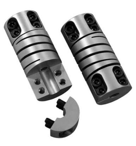
The new X-Series is a high performance, easy to use, durable, full featured, radial (cross) slot flexible coupling with high torque capacity and exceptional torsional stiffness. It is offered in six different outside diameters and a wide range of bore sizes. It features the reliable, user friendly, integral clamp attachment.
The integral clamp fasteners are located inline, on either side of the radial-slot flexing element. This provides the easiest assembly for most applications, where just moving the hex wrench across the flexing element is all it takes to tighten both fasteners.
Along with high torsional stiffness and torque capacity, the X-Series couplings are completely machined from a solid piece of material. This one piece integrity ensures that there is never a worry about wear, looseness and backlash, as found in multi-piece assemblies.
To make component assembly as easy and compact as possible, the X-Series features a bore relief. This allows shafts to be inserted into the centre of the coupling without affecting the misalignment capability of the coupling. By making the centre flexible section with a slightly larger ID than either shaft size, the shafts can be inserted into this area without contacting the flexible element ID during operation. 7075-T6 aluminium is the material of choice for the X-Series.
X-Series couplings have been subjected to rigorous reliability testing. During durablility tests, couplings are subjected to parallel offsets of up to five times their rated value and tested to failure. The XSeries couplings were tested for tens of millions of cycles at these exaggerated offsets and exhibited an exceptional premium performance capability.
Available in six outside diameter sizes, from 15mm to 50mm and any bore combination between the listed minimum and maximum. Couplings can be ordered with bores that are either millimetre, inch or combination of the two.
"ABSSAC" is a registered trade mark 2375859
All rights are reserved.
The use of this catalogue is made available to you by Abssac Limited. The exclusive right to control the use of the copyright and trademarks on this site is controlled by Abssac Limited. These may not be copied, reproduced, published, distributed, modified or otherwise used in any form including electronic copying without the express permission of Abssac Limited. Abssac Limited has made all reasonable endeavor to ensure that the material on this site is accurate. You agree that Abssac Limited, nor any other person involved in creating or providing this catalogue shall be liable for any indirect or consequential damage arising from the use of any information contained in this catalogue.
The information contained in this catalogue is provided 'as is' without warranty of any kind, either expressed or implied. Abssac Limited assumes no responsibility for errors or omissions in this catalogue or other documents which are reference by or linked to this catalogue. This catalogue could include technical or other inaccuracies including typographical errors. Updates and changes are periodically added to the information herein; these changes will be incorporated in new editions of this catalogue. Abssac Limited may make improvements and/or changes in the product(s) or service(s) described in this publication at any time. You agree that the above terms represent the entire basis of the agreement between us, upon which you are permitted to enter this site and you agree that all relations between us are subject to the Law of England and Wales.
