![]()
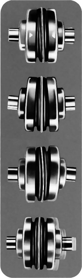
4-WAY FLEXING ACTION
absorbs all types of
shock, vibration and misalignment
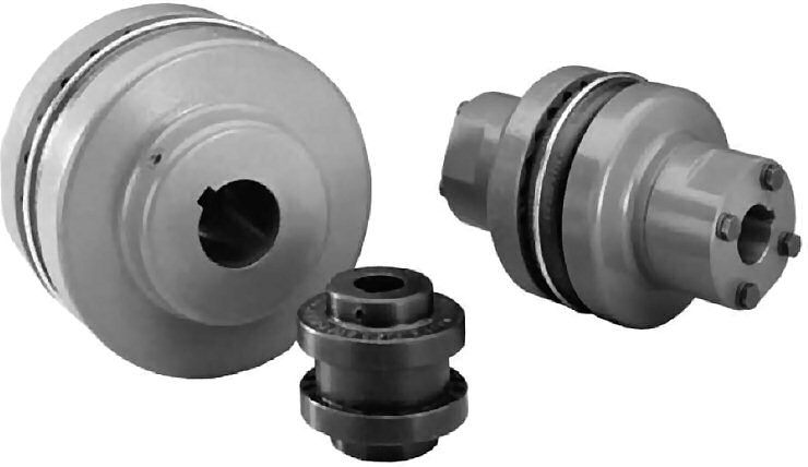
Sure-Flex coupling sleeves have an exceptional ability to absorb torsional shock and dampen torsional vibrations. The EPDM and Neoprene sleeves wind-up approximately 15" torsionally at their rated torque. Hytrel sleeves will wind-up about 7".
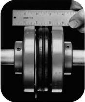
The unique design of the Sure-Flex coupling's teeth allows for the absorption of angular misalignment without wear. Alignment of the coupling requires using only a scale and calipers.
Parallel misalignment is absorbed without wear or appreciable energy losses. The lateral flexibility of the coupling sleeve minimizes radial bearing loads normally associated with parallel misalignment. This feature also allows for easier installation by the use of components bored for slip fits without fretting corrosion occurring at the shaft. Only a straight-edge and feeler gauge are required
Sure-Flex couplings may be used in applications with limited axial shaft movements. The axial compressibility of the EPDM and Neoprene sleeves allows for shaft endfloat without the absolute transfer of thrust loads.

Sure-Flex can be installed quickly and easily, because there are no bolts, gaskets, covers or seals. Alignment can be checked with a straightedge placed across the outside of the precision-machined flanges. No special tools are needed for installation, alignment or removal.
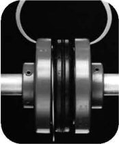
The teeth of the sleeve lock into the teeth of the flanges without clamps or screws, tightening under torque to provide smooth transmission of power. There is no rubbing action of metal against rubber to cause wear. Couplings are not affected by abrasives, dirt, or moisture. This eliminates the need for lubrication or maintenance, provides clean, dependable, quiet performance.
| • Example #1 - Close coupled | PROD. NUMBER | PROD. DESCRIPTION |
|---|---|---|
| Size 6, Type S flange w 1-3/8 bore Size 6, Type S flange w 1" bore Size 6, Solid EPDM sleeve | 6S138 6S1 6J | 6Sx1-3/8 6Sx1 6JE |
| • Example #2 - 5" Between shaft spacer | ||
| Size 9, Type SC flange for #11 hub Size 9, Type SC flange for #9 hub Size 11 hub w 2-3/8 bore Size 9 short hub w 1-1/8 bore Size 9 Solid Hytrel sleeve | 9SC5011 9SC50 11SCH238 9SCHS118 9H | 9SC50-11 9SC50 11 SCH x 2-3/8 9SCHS x 1-1/8 9H |
Sure-Flex Sleeves are available in four materials or compounds and various shape configurations.
| CONSTRUCTIONS AVAILABLE | EPDM | Neoprene | Hytrel | Urethane | |
|---|---|---|---|---|---|
| 1 pc, unsplit | JE | JN | H | U | |
| 1 pc, split | JES | JNS | - | - | |
| 2 piece | E | N | HS | - | |
| TYPICAL USE | General Purpose | Oil Resist Non-flame | General Purpose | Stiffness | |
| REL. RATING | 1X | 1X | 4X | 4X | |
| WIND-UP ANGULAR | 15° | 15° | 7° | 3° | |
| MISALIGN | 1° | 1° | 1/4° | 1/4° | |
| TEMPERATURE (F) | max | +275° | +200° | +250° | +200° |
| min | -30° | -0° | -65° | -80° | |
| Product No. | Product Description | Product No. | Product Description | Product No. | Product Description |
|---|---|---|---|---|---|
| 3J | 3JE EPDM | 4 | 4E EPDM | 6H | 6H Hytrel |
| 4J | 4JE EPDM | 5 | 5E EPDM | 7H | 7H Hytrel |
| 5J | 5JE EPDM | 6 | 6E EPDM | 8H | 8H Hytrel |
| 6J | 6JE EPDM | 7 | 7E EPDM | 9H | 9H Hytrel |
| 7J | 7JE EPDM | 8 | 8E EPDM | 10H | 10H Hytrel |
| 8J | 8JE EPDM | 9 | 9E EPDM | 11H | 11H Hytrel |
| 9J | 9JE EPDM | 10 | 10E EPDM | 12H | 12H Hytrel |
| 10J | 10JE EPDM | 11 | 11E EPDM | ||
| 12 | 12E EPDM | 6HS | 6HS Split Hytrel | ||
| 3JS | 3JES EPDM Split | 13 | 13E EPDM | 7HS | 7HS Split Hytrel |
| 4JS | 4JES EPDM Split | 14 | 14E EPDM | 8HS | 8HS Split Hytrel |
| 5JS | 5JES EPDM Split | 16 | 16E EPDM | 9HS | 9HS Split Hytrel |
| 6JS | 6JES EPDM Split | 10HS | 10HS Split Hytrel | ||
| 7JS | 7JES EPDM Split | 4N | 4N Neoprene | 11HS | 11HS Split Hytrel |
| 8JS | 8JES EPDM Split | 5N | 5N Neoprene | 12HS | 12HS Split Hytrel |
| 9JS | 9JES EPDM Split | 6N | 6N Neoprene | 13HS | 13HS Split Hytrel |
| 10JS | 10JES EPDM Split | 7N | 7N Neoprene | 14HS | 14HS Split Hytrel |
| 8N | 8N Neoprene | ||||
| 3JN | 3JN Neoprene | 9N | 9N Neoprene | 10U | 10U Urethane |
| 4JN | 4JN Neoprene | 10N | 10N Neoprene | 11U | 11U Urethane |
| 5JN | 5JN Neoprene | 11N | 11N Neoprene | 12U | 12U Urethane |
| 6JN | 6JN Neoprene | 12N | 12N Neoprene | ||
| 7JN | 7JN Neoprene | 13N | 13N Neoprene | ||
| 8JN | 8JN Neoprene | 14N | 14N Neoprene | ||
| 3JNS | 3JNS Neoprene Split | ||||
| 4JNS | 4JNS Neoprene Split | ||||
| 5JNS | 5JNS Neoprene Split | ||||
| 6JNS | 6JNS Neoprene Split | ||||
| 7JNS | 7JNS Neoprene Split | ||||
| 8JNS | 8JNS Neoprene Split | ||||
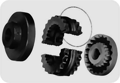
Flexible sleeves for Wood's Sure-Flex couplings are available in four materials (EPDM Neoprene, Hytrel and Urethane) and in three basic constructions.
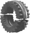
 | 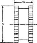 | 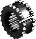 | JE-JES-JN-JNSJ sleeves are molded EPDM rubber (E) or Neoprene (N). They are available in one-piece solid construction (JE, IN) or one· piece split construction (JES, JNS). These sleeves may be used in any Sure-Flex flange within a given size. |
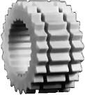
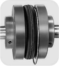
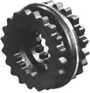 |  |  | E-NThese sleeves are of two-piece design with a retaining ring. They are available in either EPDM (E) or Neoprene (N). They may be used with any flange within a given size. Sleeves are shown here assembled and disassembled. |
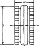
 |  | 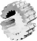 | H-HS-UH (Hytrel) and U (Urethane) sleeves, designed for high-torque applications, transmit four times as much power as an equivalent EPDM or Neoprene sleeve. Available in one-piece solid construction (H or U) or two·piece split construction (HS), these can be used only with S, C and SC flanges. They cannot be used with J or B flanges or as direct replacements for EPDM or Neoprene sleeves. |
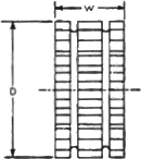
| Coupling Size | JE, JES, JN & JNS Sleeves EPDM & Neoprene | E and N Sleeves EPDM & Neoprene | H, U & HS Sleeves Hytrel & Urethane | ||||||
|---|---|---|---|---|---|---|---|---|---|
| D | W | Wt. (lbs.) | D | W | Wt. (lbs.) | D | W | Wt. (lbs.) | |
| 3 | 1 7/8 | 1 | .06 | ||||||
| 4 | 2 5/16 | 1 1/4 | .10 | 2 5/16 | 1 1/4 | .11 | |||
| 5 | 2 15/16 | 1 9/16 | .20 | 2 15/16 | 1 9/16 | .25 | |||
| 6 | 3 3/4 | 1 7/8 | .40 | 3 3/4 | 1 7/8 | .49 | 3 3/4 | 1 7/8 | .44 |
| 7 | 4 11/32 | 2 3/16 | .62 | 4 11/32 | 2 3/16 | .77 | 4 11/32 | 2 3/16 | .69 |
| 8 | 5 1/16 | 2 1/2 | 1.13 | 5 1/16 | 2 1/2 | 1.4 | 5 1/16 | 2 1/2 | 1.4 |
| 9* | 6 | 3 | 1.46 | 6 | 3 | 2.0 | 6 | 3 | 1.8 |
| 10* | 7 1/16 | 3 7/16 | 2.32 | 7 1/16 | 3 7/16 | 3.2 | 7 1/16 | 3 7/16 | 2.9 |
| 11 | 8 3/16 | 4 | 5.1 | 8 3/16 | 4 | 4.5 | |||
| 12 | 9 9/16 | 4 11/16 | 8.1 | 9 9/16 | 4 11/16 | 7.3 | |||
| 13 | 11 3/16 | 5 1/2 | 13.0 | 11 3/16 | 5 1/2 | 11.8 | |||
| 14 | 13 3/32 | 6 1/2 | 21.1 | 13 3/32 | 6 1/2 | 19.3 | |||
| 16 | 17 29/32 | 8 3/4 | 45.3 | ||||||
| The 13 and 14 Hytrel available with HS sleeves only. | |||||||||
| *All 9J and 10J sleeves available in EPDM only. | Only sizes available in Urethane. | ||||||||
| Application | Load Symbol | Application | Load Symbol | Application | Load Symbol |
|---|---|---|---|---|---|
| AGITATORS-Paddle, Propeller, Screw | L | DEWATERING SCREEN (sewage) | M | MILLS | |
| BAND RESAW (lumber) | M | DISC FEEDER | L | Ball, Pebble, Rod, Tube, Rubber Tumbling | H |
| BARGE HAUL PULLER . | H | DOUGH MIXER | M | Dryer and Cooler | M |
| BARKING (lumber) | H | DRAW BENCH CONVEYOR and MAIN DRIVE | H | MIXERS | |
| BAR SCREEN (sewage) | L | DREDGES | Concrete, Muller | M | |
| BATCHES (textile) | L | Cable Reel, Pumps | M | Banbury | H |
| BEATER AND PULPER (paper) | M | Cutter Head Drive, Jig Drive, Screen Drive | H | ORE CRUSHER | H |
| BENDING ROLL (metal) | M | Maneuvering and Utility Winch, Stacker | M | OVEN CONVEYOR | L |
| BLEACHER (paper) | L | DYNAMOMETER | L | PLANER (metal or wood) | M |
| BLOWERS | DRYERS (rotary) | M | PRESSES | ||
| Centrifugal, Vane | L | EDGER (lumber) | H | Brick, Briquette Machine | H |
| Lobe | M | ELEVATOR | Notching, Paper, Punch, Printing | M | |
| BOTTLING MACHINERY | L | Bucket | M | PUG MILL | M |
| BREW KETTLES (distilling) | L | Escalator | L | PULP GRINDER (paper) | H |
| BUCKET ELEVATOR OR CONVEYOR | M | Freight, Passenger, Service, Man Lift | H | PULVERIZERS | |
| CALENDERS | ESCALATORS | L | Hammermill-light duty, Roller | M | |
| Calendar (paper) | M | EXTRUDER (metal) | H | Hammermill-heavy duty, Hog | H |
| Calender-super (paper), Calender (rubber) | H | FANS | PUMPS | ||
| CANE KNIVES (sugar) | M | Centrifugal | L | Centrifugal, Axial | L |
| CARD MACHINE (textile) | H | Cooling Tower | H | Gear, Lobe, Vane | M |
| CAR DUMPERS | H | Forced Draft, Large Industrial or Mine | M | Reciprocating - sgl. or dbl. acting, cylinder | * |
| CAR PULLERS | M | FEEDERS | REEL, REWINDER (paper) CABLE | M | |
| CEMENT KILN | H | Apron, Belt, Disc | L | ROD MILL | H |
| CENTRIFUGAL BLOWERS, COMPRESSORS, FANS or PUMPS | L | Reciprocating | H | SAWDUST CONVEYOR | L |
| CHEMICAL FEEDERS (sewage) | L | Screw | M | SCREENS | |
| CHILLER (oil) | M | FILTER, PRESS-OIL | M | Air Washing, Water | L |
| CHIPPER (paper) | H | GENERATORS | Rotary for coal or sand | M | |
| CIRCULAR RESAW (lumber) | M | Uniform load | L | Vibrating | H |
| CLARIFIER or CLASSIFIER | L | Varying load, Hoist | M | SCREW CONVEYOR | L |
| CLAY WORKING MACHINERY | M | Welders | H | SLAB CONVEYOR (lumber) | M |
| COLLECTORS (sewage) | L | GRIT COLLECTOR (sewage) | L | SLITTERS (metal) | M |
| COMPRESSORS | GRIZZLY | H | SOAPERS (textile) | L | |
| Centrifugal | L | HAMMERMILL | SORTING TABLE (lumber) | M | |
| Reciprocating | * | Light Duty, Intermittent | M | SPINNER (textile) | M |
| Screw, Lobe | L | Heavy Duty, Continuous | H | STOKER | L |
| CONCRETE MIXERS | M | HOISTS | SUCTION ROLL (paper) | M | |
| CONVERTING MACHINE (paper) | M | Heavy Duty | H | TENTER FRAMES (textile) | M |
| CONVEYORS | Medium Duty | M | TIRE BUILDING MACHINES | H | |
| Apron, Assembly Belt, Flight, Oven, Screw | L | JORDAN (paper) | H | TIRE & TUBE PRESS OPENER | L |
| Bucket | M | KILN, ROTARY | H | TUMBLING BARRELS | H |
| COOKERS-Brewing, Distilling, Food | L | LAUNDRY WASHER or TUMBLER | H | WASHER and THICKENER (paper) | M |
| COOLING TOWER FANS | H | LINE SHAFTS | L | WINCHES | M |
| COUCH (paper) | M | LOG HAUL (lumber) | H | WINDERS, Paper, Textile, Wire | M |
| CRANES and HOISTS | M | LOOM (textile) | M | WINDLASS | M |
| Heavy Duty Mine | H | MACHINE TOOLS, MAIN DRIVE | M | WIRE | |
| CRUSHERS-Cane (sugar), Stone or Ore | H | MANGLE (textile) | L | Drawing | H |
| CUTTER-Paper | H | MASH TUBS (distilling) | L | Winding | M |
| CYLINDER (paper) | H | MEAT GRINDER | M | WOODWORKING MACHINERY | L |
| METAL FORMING MACHINES | M | ||||
| *Consult Factory | |||||
| Load Symbol | L Light | M Medium | H Heavy |
|---|---|---|---|
| Standard AC Motor DC Shunt Motor *Engine, 8 or more cylinders | 1.25 | 1.5 | 2.0 |
| High Torque AC Motor DC Series & Comp. *Engine, 4-6 cylinders | 1.5 | 2.0 | 2.5 |
| *Engine, 3 cylinders or less | 2.0 | 2.5 | 3.0 |
| Turbine | 1.0 | 1.25 | 1.5 |
*On applications involving varying torque loads, design around the maximum load. Then determine the resulting service factor at minimum load. If this value is greater than 4.0, special coupling alignment will be required (see page F1-18).
Caution: Applications involving reciprocating engines and reciprocating driven devices are subject to rotational vibrational critical speeds which may destroy the coupling. The factory can determine these speeds when the rotational inertia (WR2) of the driveR and driveN units is known.
Example: For 150 HP @ 1750 RPM and 1.5 Service Factor - Use #13 EPDM or Neoprene or #10 Hytrel or Urethane.
HP @ 100 rpm = HP x Service Factor x 100/ coupling RPM
Example: For 5 HP @ 55 RPM and 1.25 Service Factor:
HP @ 100 = 5 x 1.25 x 100/55 = 11.36
Use #12 EPDM or Neoprene or #9 Hytrel with rating of 11.4 HP.
| Size | EPDM Sleeves | Neoprene Sleeves | HP @ RPM | Torque (in. lbs.) | Stiffness (in. lbs./rad) | Max RPM | |||
|---|---|---|---|---|---|---|---|---|---|
| 100 | 1160 | 1750 | 3500 | ||||||
| 3 | JE, JES | IN, JNS | 0.1 | 1.4 | 2.2 | 4.3 | 78 | 229 | 9200 |
| 4 | E, JE, JES | N, JN, JNS | 0.2 | 2.9 | 4.3 | 8.7 | 156 | 458 | 7600 |
| 5 | E, JE, JES | N, JN, JNS | 0.5 | 5.7 | 8.7 | 17 | 312 | 916 | 7600 |
| 6 | E, JE, JES | N, JN, JNS | 0.9 | 11 | 16 | 32 | 585 | 1718 | 6000 |
| 7 | E, JE, JES | N, JN, JNS | 1.5 | 17 | 26 | 52 | 940 | 2769 | 5250 |
| 8 | E, JE, JES | N, JN, JNS | 2.3 | 27 | 41 | 82 | 1475 | 4335 | 4500 |
| 9 | E, JE, JES | N | 3.7 | 43 | 65 | 130 | 2340 | 6875 | 3750 |
| 10 | E, JE, JES | N | 5.9 | 69 | 104 | 208 | 3735 | 10980 | 3600 |
| 11 | E | N | 9.3 | 108 | 164 | 327 | 5890 | 17300 | 3600 |
| 12 | E | N | 15 | 172 | 260 | 9360 | 27500 | 2800 | |
| 13 | E | N | 23 | 272 | 410 | 14750 | 43350 | 2400 | |
| 14 | E | N | 37 | 431 | 650 | 23400 | 68755 | 2200 | |
| 16 | E | 75 | 870 | 47250 | 180480 | 1500 | |||
| Size | Hytrel Sleeves | Urethane Sleeves | HP @ RPM | Torque (in. lbs.) | Stiffness (in. lbs./rad) | Max RPM | |||
| 100 | 1160 | 1750 | 3500 | ||||||
| 6 | H, HS | 2.9 | 33 | 50 | 100 | 1800 | 10000 | 6000 | |
| 7 | H, HS | 4.6 | 53 | 80 | 160 | 2875 | 20000 | 5250 | |
| 8 | H, HS | 7.2 | 84 | 126 | 252 | 4530 | 30000 | 4500 | |
| 9 | H, HS | 11 | 132 | 200 | 400 | 7200 | 47500 | 3750 | |
| 10 | H, HS | U | 18 | 209 | 315 | 630 | 11350 | 100000* | 3600 |
| 11 | H, HS | U | 29 | 331 | 500 | 1000 | 18000 | 125000* | 3600 |
| 12 | H, HS | U | 50 | 580 | 875 | 31500 | 225000* | 2800 | |
| 13 | HS | 75 | 870 | 1312 | 47268 | 368900 | 2400 | ||
| 14 | HS | 115 | 1334 | 2013 | 72480 | 593250 | 2200 | ||
| * Urethane values are 220000, 350000, and 600000. | |||||||||
| 860 RPM MOTORS | 1160 RPM MOTORS | 1750 RPM MOTORS | 3500 RPM MOTORS | ||||||||||||||||||||
|---|---|---|---|---|---|---|---|---|---|---|---|---|---|---|---|---|---|---|---|---|---|---|---|
| HP | Service Factors | HP | Service Factors | HP | Service Factors | HP | Service Factors | ||||||||||||||||
| 1.0 | 1.25 | 1.5 | 2.0 | 2.5 | 1.0 | 1.25 | 1.5 | 2.0 | 2.5 | 1.0 | 1.25 | 1.5 | 2.0 | 2.5 | 1.0 | 1.25 | 1.5 | 2.0 | 2.5 | ||||
| ½ | 3 | 3 | 3 | 3 | 4 | ½ | 3 | 3 | 3 | 3 | 3 | ½ | 3 | 3 | 3 | 3 | 3 | ½ | 3 | 3 | 3 | 3 | 3 |
| ¾ | 3 | 3 | 3 | 4 | 4 | ¾ | 3 | 3 | 3 | 4 | 4 | ¾ | 3 | 3 | 3 | 3 | 3 | ¾ | 3 | 3 | 3 | 3 | 3 |
| 1 | 3 | 4 | 4 | 4 | 5 | 1 | 3 | 3 | 4 | 4 | 4 | 1 | 3 | 3 | 3 | 3 | 4 | 1 | 3 | 3 | 3 | 3 | 3 |
| 1 ½ | 4 | 4 | 5 | 5 | 5 | 1 ½ | 4 | 4 | 4 | 5 | 5 | 1 ½ | 3 | 3 | 4 | 4 | 4 | 1 ½ | 3 | 3 | 3 | 3 | 3 |
| 2 | 4 | 5 | 5 | 5 | 6 | 2 | 4 | 4 | 5 | 5 | 5 | 2 | 3 | 4 | 4 | 4 | 5 | 2 | 3 | 3 | 3 | 3 | 4 |
| 3 | 5 | 5 | 6 | 6 | 6 | 3 | 5 | 5 | 5 | 6 | 6 | 3 | 4 | 4 | 5 | 5 | 5 | 3 | 3 | 3 | 4 | 4 | 4 |
| 5 | 6 | 6 | 6 | 7 | 7 | 5 | 5 | 6 | 6 | 6 | 7 | 5 | 5 | 5 | 5 | 6 | 6 | 5 | 4 | 4 | 4 | 5 | 5 |
| 7 ½ | 6 | 7 | 7 | 8 | 8 | 7 ½ | 6 | 6 | 7 | 7 | 8 | 7 ½ | 5 | 6 | 6 | 6 | 7 | 7 ½ | 4 | 5 | 5 | 5 | 6 |
| 10 | 7 | 7 | 8 | 8 | 9 | 10 | 6 | 7 | 7 | 8 | 8 | 10 | 6 | 6 | 6 | 7 | 7 | 10 | 5 | 5 | 5 | 6 | 6 |
| 15 | 8 | 8 | 9 | 9 | 10 | 15 | 7 | 8 | 8 | 9 | 9 | 15 | 6 | 7 | 7 | 8 | 8 | 15 | 5 | 6 | 6 | 6 | 7 |
| 20 | 8 | 9 | 9 | 10 | 10 | 20 | 8 | 8 | 9 | 9 | 10 | 20 | 7 | 7 | 8 | 8 | 9 | 20 | 6 | 6 | 6 | 7 | 7 |
| 25 | 9 | 9 | 10 | 10 | 11 | 25 | 8 | 9 | 9 | 10 | 10 | 25 | 7 | 8 | 8 | 9 | 9 | 25 | 6 | 6 | 7 | 7 | 8 |
| 30 | 9 | 10 | 10 | 11 | 11 | 30 | 9 | 9 | 10 | 10 | 11 | 30 | 8 | 8 | 9 | 9 | 10 | 30 | 6 | 7 | 7 | 8 | 8 |
| 40 | 10 | 10 | 11 | 11 | 12 | 40 | 9 | 10 | 10 | 11 | 11 | 40 | 8 | 9 | 9 | 10 | 10 | 40 | 7 | 7 | 8 | 8 | 9 |
| 50 | 10 | 11 | 11 | 12 | 12 | 50 | 10 | 10 | 11 | 11 | 12 | 50 | 9 | 9 | 10 | 10 | 11 | 50 | 7 | 8 | 8 | 9 | 9 |
| 60 | 11 | 11 | 12 | 12 | 13 | 60 | 10 | 11 | 11 | 12 | 12 | 60 | 9 | 10 | 10 | 11 | 11 | 60 | 8 | 8 | 9 | 9 | 10 |
| 75 | 11 | 12 | 12 | 13 | 13 | 75 | 11 | 11 | 12 | 12 | 13 | 75 | 10 | 10 | 11 | 11 | 12 | 75 | 8 | 9 | 9 | 10 | 10 |
| 100 | 12 | 12 | 13 | 13 | 14 | 100 | 11 | 12 | 12 | 13 | 13 | 100 | 10 | 11 | 11 | 12 | 12 | 100 | 9 | 9 | 10 | 10 | 11 |
| 125 | 12 | 13 | 13 | 14 | 14 | 125 | 12 | 12 | 13 | 13 | 14 | 125 | 11 | 11 | 12 | 12 | 13 | 125 | 9 | 10 | 10 | 11 | 11 |
| 150 | 13 | 13 | 14 | 14 | 16 | 150 | 12 | 13 | 13 | 14 | 14 | 150 | 11 | 12 | 12 | 13 | 13 | 150 | 10 | 10 | 11 | 11 | |
| 200 | 13 | 14 | 14 | 16 | 16 | 200 | 13 | 13 | 14 | 14 | 16 | 200 | 12 | 12 | 13 | 13 | 14 | 200 | 10 | 11 | 11 | ||
| 250 | 14 | 14 | 16 | 16 | 16 | 250 | 13 | 14 | 14 | 16 | 16 | 250 | 12 | 13 | 13 | 14 | 14 | 250 | 11 | 11 | |||
| 300 | 14 | 16 | 16 | 16 | 16 | 300 | 14 | 14 | 16 | 16 | 16 | 300 | 13 | 13 | 14 | 14 | 300 | 11 | |||||
| 350 | 16 | 16 | 16 | 16 | 350 | 14 | 16 | 16 | 16 | 16 | 350 | 13 | 14 | 14 | 350 | ||||||||
| 400 | 16 | 16 | 16 | 400 | 14 | 16 | 16 | 16 | 16 | 400 | 13 | 14 | 14 | 400 | |||||||||
| 450 | 16 | 16 | 450 | 16 | 16 | 450 | 14 | 450 | |||||||||||||||
| 500 | 16 | 16 | 500 | 16 | 16 | 500 | 14 | 500 | |||||||||||||||
| 600 | 16 | 600 | 16 | 600 | 600 | ||||||||||||||||||
| 700 | 700 | 700 | 700 | ||||||||||||||||||||
| 800 | 800 | 800 | 800 | ||||||||||||||||||||
| 860 RPM MOTORS | 1160 RPM MOTORS | 1750 RPM MOTORS | 3500 RPM MOTORS | ||||||||||||||||||||
|---|---|---|---|---|---|---|---|---|---|---|---|---|---|---|---|---|---|---|---|---|---|---|---|
| HP | Service Factors | HP | Service Factors | HP | Service Factors | HP | Service Factors | ||||||||||||||||
| 1.0 | 1.25 | 1.5 | 2.0 | 2.5 | 1.0 | 1.25 | 1.5 | 2.0 | 2.5 | 1.0 | 1.25 | 1.5 | 2.0 | 2.5 | 1.0 | 1.25 | 1.5 | 2.0 | 2.5 | ||||
| 7 ½ | 6 | 6 | 6 | 6 | 6 | 7 ½ | 7 ½ | 7 ½ | |||||||||||||||
| 10 | 6 | 6 | 6 | 6 | 6 | 10 | 6 | 6 | 6 | 6 | 6 | 10 | 10 | ||||||||||
| 15 | 6 | 6 | 6 | 7 | 7 | 15 | 6 | 6 | 6 | 6 | 7 | 15 | 6 | 6 | 6 | 6 | 6 | 15 | |||||
| 20 | 6 | 6 | 7 | 7 | 8 | 20 | 6 | 6 | 6 | 7 | 7 | 20 | 6 | 6 | 6 | 6 | 6 | 20 | |||||
| 25 | 6 | 7 | 7 | 8 | 8 | 25 | 6 | 6 | 7 | 7 | 8 | 25 | 6 | 6 | 6 | 6 | 7 | 25 | |||||
| 30 | 7 | 7 | 8 | 8 | 9 | 30 | 6 | 7 | 7 | 8 | 8 | 30 | 6 | 6 | 6 | 7 | 7 | 30 | 6 | 6 | 6 | 6 | 6 |
| 40 | 7 | 8 | 8 | 9 | 9 | 40 | 7 | 7 | 8 | 8 | 9 | 40 | 6 | 6 | 7 | 7 | 8 | 40 | 6 | 6 | 6 | 6 | 6 |
| 50 | 8 | 8 | 9 | 9 | 10 | 50 | 7 | 8 | 8 | 9 | 9 | 50 | 6 | 7 | 7 | 8 | 8 | 50 | 6 | 6 | 6 | 6 | 7 |
| 60 | 8 | 9 | 9 | 10 | 10 | 60 | 8 | 8 | 9 | 9 | 10 | 60 | 7 | 7 | 8 | 8 | 9 | 60 | 6 | 6 | 6 | 7 | 7 |
| 75 | 9 | 9 | 10 | 10 | 11 | 75 | 8 | 9 | 9 | 10 | 10 | 75 | 7 | 8 | 8 | 9 | 9 | 75 | 6 | 6 | 7 | 7 | 8 |
| 100 | 9 | 10 | 10 | 11 | 11 | 100 | 9 | 9 | 10 | 10 | 11 | 100 | 8 | 8 | 9 | 9 | 10 | 100 | 6 | 7 | 7 | 8 | 8 |
| 125 | 10 | 10 | 11 | 11 | 12 | 125 | 9 | 10 | 10 | 11 | 11 | 125 | 8 | 9 | 9 | 10 | 10 | 125 | 7 | 7 | 8 | 8 | 9 |
| 150 | 10 | 11 | 11 | 12 | 12 | 150 | 10 | 10 | 11 | 11 | 12 | 150 | 9 | 9 | 10 | 10 | 11 | 150 | 7 | 8 | 8 | 9 | 9 |
| 200 | 11 | 11 | 12 | 12 | 13 | 200 | 10 | 11 | 11 | 12 | 12 | 200 | 9 | 10 | 10 | 11 | 11 | 200 | 8 | 8 | 9 | 9 | 10 |
| 250 | 11 | 12 | 12 | 13 | 13 | 250 | 11 | 11 | 12 | 12 | 13 | 250 | 10 | 10 | 11 | 11 | 12 | 250 | 8 | 9 | 9 | 10 | 10 |
| 300 | 12 | 12 | 13 | 13 | 14 | 300 | 11 | 12 | 12 | 13 | 13 | 300 | 10 | 11 | 11 | 12 | 12 | 300 | 9 | 9 | 10 | 10 | 11 |
| 350 | 12 | 12 | 13 | 14 | 14 | 350 | 12 | 12 | 12 | 13 | 14 | 350 | 11 | 11 | 12 | 12 | 12 | 350 | 9 | 10 | 10 | 11 | 11 |
| 400 | 12 | 13 | 13 | 14 | 14 | 400 | 12 | 12 | 13 | 13 | 14 | 400 | 11 | 11 | 12 | 12 | 13 | 400 | 9 | 10 | 10 | 11 | 11 |
| 500 | 13 | 13 | 14 | 14 | 500 | 12 | 13 | 13 | 14 | 14 | 500 | 11 | 12 | 12 | 13 | 13 | 500 | 10 | 10 | 11 | 11 | ||
| 600 | 13 | 14 | 14 | 600 | 13 | 13 | 13 | 14 | 600 | 12 | 12 | 13 | 13 | 14 | 600 | 10 | 11 | 11 | |||||
| 700 | 14 | 14 | 700 | 13 | 13 | 14 | 14 | 700 | 12 | 12 | 13 | 14 | 14 | 700 | 11 | 11 | |||||||
| 800 | 14 | 14 | 800 | 13 | 14 | 14 | 800 | 12 | 13 | 13 | 14 | 14 | 800 | 11 | 11 | ||||||||
| 900 | 14 | 900 | 14 | 14 | 14 | 900 | 13 | 13 | 14 | 14 | 900 | 11 | |||||||||||
| 1000 | 1000 | 14 | 14 | 1000 | 13 | 13 | 14 | 14 | 1000 | 11 | |||||||||||||
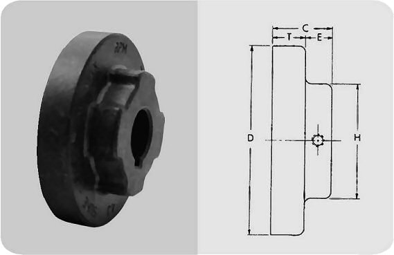
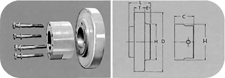
Type J flanges size 3 and 4 are manufactured of sintered carbon steel. The powdered metal manufacturing process provides high dimensional accuracy and uniform material properties for high strength. Size 5 and 6 are made of high strength cast iron. All flanges are bored-to-size for a slip fit on standard shafts. The outside diameter of the flange is machined so the surface can be used to check alignment without a special tool. Type J flanges can be used with sleeves of any construction except the Hytrel. Each flange has a keyseat and one (1) setscrew over the keyway.
Type J Sure-Flex Couplings are bored-to-size. Normally, they employ the one-piece JE sleeve, or the onepiece JES sleeve with saw cut to permit replacement where there is Insufficient gap between shafts.
Spacing between internal flange hubs equals G. Spacing between shafts should be greater tnan 1/8 in. and less than L minus .85 times the sum of the two bore diameters.
| Product No. | Dimensions | Wt. (lbs.) ■ | (Inches) | Max Bore | Millimeters | ||||||||||||||||||||||||||
|---|---|---|---|---|---|---|---|---|---|---|---|---|---|---|---|---|---|---|---|---|---|---|---|---|---|---|---|---|---|---|---|
| C | D | E | G | H | L | T | X | 3⁄8 | 1⁄2 | 5⁄8 | 3⁄4 | 7⁄8 | 15⁄16 | 1 | 11⁄8 | 13⁄16 | 11⁄4 | 13⁄8 | 9 | 11 | 12 | 14 | 15 | 16 | 19 | 20 | 24 | 25 | |||
| 3J | 51⁄64 | 2.062 | 13⁄32 | 3⁄8 | 11⁄2 | 131⁄32 | 25⁄64 | 5⁄8 | 0.3 | • | • | • | • | • | 7⁄8 | • | • | • | • | • | • | ||||||||||
| 4J | 55⁄64 | 2.500 | 27⁄64 | 5⁄8 | 15⁄8 | 211⁄32 | 7⁄16 | 5⁄8 | 0.4 | • | • | • | • | • | • | 1 | • | • | • | • | • | • | • | ||||||||
| 5J | 13⁄64 | 3.250 | 29⁄64 | 3⁄4 | 17⁄8 | 227⁄32 | 19⁄32 | 59⁄64 | 0.9 | • | • | • | • | • | • | • | 11⁄8 | ||||||||||||||
| 6J | 15⁄16 | 4.000 | 9⁄16 | 7⁄8 | 21⁄2 | 31⁄2 | 3⁄4 | 13⁄32 | 1.2 | • | • | • | • | • | • | • | • | • | 13⁄8 | ||||||||||||
| *We do not recommend reboring the 3J and 4J Flanges. See page F1-13 for standard keyseat dimensions & F1-10 for bore tolerances. ■ Approximate weight for each flange. | |||||||||||||||||||||||||||||||
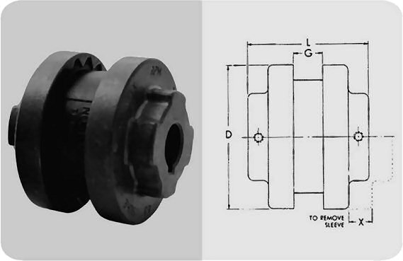
Type S flanges are made of high-strength cast iron and are bored-to-size for slip fit on standard shafts. They are easy to install and remove, and are available from stock in a wide range of bore sizes.
| Bore (in.) | Tolerance (in.) |
|---|---|
| Up to and including 2" | + .0005 to + .0015 |
| Over 2" | + .0005 to +.0020 |
| Product No. | Dimensions | Wt. (lbs.) ■ | STOCK BORES ① Inches | ||||||||||||||||||||||||||||||||||||||||||||
|---|---|---|---|---|---|---|---|---|---|---|---|---|---|---|---|---|---|---|---|---|---|---|---|---|---|---|---|---|---|---|---|---|---|---|---|---|---|---|---|---|---|---|---|---|---|---|---|
| C | D | E | G | H | L | T | X | 1 ⁄ 2 | 5 ⁄ 8 | 3 ⁄ 4 | 13 ⁄ 16 | 7 ⁄ 8 | 15 ⁄ 16 | 1 | 1 1 ⁄ 16 | 1 1 ⁄ 8 | 1 3 ⁄ 16 | 1 1 ⁄ 4 | 1 5 ⁄ 16 | 1 3 ⁄ 8 | 1 7 ⁄ 16 | 1 1 ⁄ 2 | 1 9 ⁄ 16 | 1 5 ⁄ 8 | 1 11 ⁄ 16 | 1 3 ⁄ 4 | 1 7 ⁄ 8 | 1 15 ⁄ 16 | 2 | 2 1 ⁄ 16 | 2 1 ⁄ 8 | 2 3 ⁄ 16 | 2 1 ⁄ 4 | 2 3 ⁄ 8 | 2 7 ⁄ 16 | 2 1 ⁄ 2 | 2 5 ⁄ 8 | 2 3 ⁄ 4 | 2 7 ⁄ 8 | 3 | 3 3 ⁄ 8 | 3 7 ⁄ 16 | 3 5 ⁄ 8 | 3 7 ⁄ 8 | 3 15 ⁄ 16 | ||
| 5S | 111⁄32 | 3.250 | 29⁄64 | 23⁄32 | 17⁄8 | 213⁄16 | 19⁄32 | 31⁄32 | 1.1 | ○ | • | • | • | • | • | • | • | • | • | • | |||||||||||||||||||||||||||
| 6S | 15⁄8 | 4.000 | 17⁄32 | 7⁄8 | 21⁄2 | 31⁄2 | 25⁄32 | 13⁄32 | 1.9 | ○ | • | • | • | • | • | • | • | • | • | • | • | • | |||||||||||||||||||||||||
| 15⁄16 | 4.000 | 17⁄32 | 7⁄8 | 21⁄2 | 31⁄2 | 25⁄32 | 13⁄32 | 1.8 | • | • | |||||||||||||||||||||||||||||||||||||
| 19⁄16 | 4.000 | 25⁄32 | 7⁄8 | 213⁄16 | 4 | 25⁄32 | 13⁄32 | 1.8 | • | ||||||||||||||||||||||||||||||||||||||
| 7S | 127⁄32 | 4.625 | 11⁄16 | 1 | 213⁄16 | 315⁄16 | 25⁄32 | 15⁄16 | 2.6 | ○ | • | • | • | • | • | • | • | • | • | • | • | • | • | • | |||||||||||||||||||||||
| 8S | 23⁄32 | 5.450 | 3⁄4 | 11⁄8 | 31⁄4 | 47⁄16 | 29⁄32 | 11⁄2 | 4.4 | ○ | • | • | • | • | • | • | • | • | • | • | • | • | • | • | • | • | • | • | • | ||||||||||||||||||
| 115⁄16 | 5.450 | 11⁄32 | 11⁄8 | 31⁄4 | 5 | 29⁄32 | 11⁄2 | 3.7 | • | ||||||||||||||||||||||||||||||||||||||
| 9S | 213⁄32 | 6.350 | 25⁄32 | 17⁄16 | 35⁄8 | 51⁄16 | 11⁄32 | 13⁄4 | 6.8 | ○ | • | • | • | • | • | • | • | • | • | • | • | • | • | • | • | • | • | • | • | • | • | ||||||||||||||||
| 29⁄32 | 6.350 | 11⁄4 | 17⁄16 | 41⁄8 | 6 | 11⁄32 | 13⁄4 | 6.2 | • | ||||||||||||||||||||||||||||||||||||||
| 10S | 223⁄32 | 7.500 | 13⁄16 | 15⁄8 | 43⁄8 | 511⁄16 | 17⁄32 | 2 | 10.5 | ○ | • | • | • | • | • | • | • | • | • | • | • | • | • | • | • | • | • | • | • | • | • | • | |||||||||||||||
| 211⁄16 | 7.500 | 115⁄32 | 15⁄8 | 43⁄4 | 7 | 17⁄32 | 2 | 9.8 | • | ||||||||||||||||||||||||||||||||||||||
| 11S | 37⁄16 | 8.625 | 11⁄8 | 17⁄8 | 51⁄4 | 71⁄8 | 11⁄2 | 23⁄8 | 16.6 | ○ | • | • | • | • | • | • | • | • | • | • | • | • | • | • | • | • | |||||||||||||||||||||
| 31⁄16 | 8.625 | 19⁄16 | 17⁄8 | 55⁄8 | 8 | 11⁄2 | 23⁄8 | 16.4 | • | ||||||||||||||||||||||||||||||||||||||
| 12S | 4 | 10.000 | 19⁄32 | 25⁄16 | 53⁄4 | 81⁄4 | 111⁄16 | 211⁄16 | 26.6 | ○ | • | • | • | • | • | • | • | • | • | • | • | • | • | ||||||||||||||||||||||||
| 13S | 43⁄8 | 11.750 | 15⁄16 | 211⁄16 | 63⁄4 | 91⁄4 | 131⁄32 | 31⁄16 | 45.2 | ○ | • | • | • | • | • | • | |||||||||||||||||||||||||||||||
| 14S | 41⁄2 | 13.875 | 11⁄16 | 31⁄4 | 71⁄2 | 97⁄8 | 21⁄4 | 31⁄2 | 69.1 | ○ | • | • | |||||||||||||||||||||||||||||||||||
| 16S | 6 | 18.875 | 2 | 43⁄4 | 8 | 141⁄4 | 23⁄4 | 41⁄4 | 125.3 | ○ | |||||||||||||||||||||||||||||||||||||
• in the chart denotes finished bore with keyseat and 2 setscrews; ○ is plain bore suitable for reboring .
■ Approximate weight for each flange.
Type S Sure-Flex couplings are normally supplied with the two-piece E sleeve. However, any of the sleeves can be used with Type S flanges.
Spacing between internal flange hubs equals L minus 2 times C. Spacing between shafts should be greater than 1/8 in. and less than L minus .85 times the sum of the two bore diameters.
| STOCK BORES | Max. Bore | SHALLOW KEYSEAT DIMENSIONS ② | |||||||||||||||||||||||||||||||
|---|---|---|---|---|---|---|---|---|---|---|---|---|---|---|---|---|---|---|---|---|---|---|---|---|---|---|---|---|---|---|---|---|---|
| Millimeters | ① Standard Keyseat | ② Shallow Keyseat | |||||||||||||||||||||||||||||||
| 14 | 15 | 16 | 19 | 20 | 24 | 25 | 28 | 30 | 32 | 35 | 38 | 42 | 45 | 48 | 50 | 52 | 55 | 60 | 65 | 70 | 80 | 90 | Bore | K.S. | Key | Bore | K.S. | Key | Bore | K.S. | Key | ||
| • | • | • | • | • | • | • | • | 13⁄16 | 11⁄4 | 11⁄4 | 1⁄4 x 1⁄16 | 1⁄4 x 3⁄16 x 13⁄8 | |||||||||||||||||||||
| • | • | • | • | • | • | • | • | • | • | 17⁄16 | 11⁄2 | ||||||||||||||||||||||
| 13⁄4 | 11⁄2 & 15⁄8 | 3⁄8 x 1⁄8 | 3⁄4 x 5⁄16 x ▲ | 13⁄4 | 3⁄8 x 1⁄16 | 3⁄8 x 1⁄4 x 11⁄4 | |||||||||||||||||||||||||||
| 17⁄8 | 17⁄8 | 1⁄2 x 1⁄16 | 1⁄2 x 5⁄16 x 19⁄16 | ||||||||||||||||||||||||||||||
| • | • | • | • | • | • | • | • | • | 15⁄8 | 17⁄8 | 17⁄8 | 1⁄2 x 1⁄8 | 1⁄2 x 3⁄8 x 17⁄8 | ||||||||||||||||||||
| • | • | • | • | • | • | • | • | 115⁄16 | 21⁄4 | 21⁄8 | 1⁄2 x 3⁄16 | 1⁄2 x 7⁄16 x 21⁄8 | |||||||||||||||||||||
| 23⁄8 | 23⁄8 | 5⁄8 x 1⁄8 | 5⁄8 x 7⁄16 x 17⁄8 | ||||||||||||||||||||||||||||||
| • | • | • | • | • | • | • | 21⁄2 | 23⁄4 | |||||||||||||||||||||||||
| 27⁄8 | 27⁄8 | 3⁄4 x 1⁄8 | 3⁄4 x 1⁄2 x 21⁄4 | ||||||||||||||||||||||||||||||
| • | • | • | • | • | • | • | • | • | • | • | 23⁄4 | 31⁄8 | 27⁄8 | 3⁄4 x 1⁄4 | 3⁄4 x 5⁄8 x 23⁄4 | ||||||||||||||||||
| 33⁄8 | 33⁄8 | 7⁄8 x 3⁄16 | 7⁄8 x 5⁄8 x 25⁄8 | ||||||||||||||||||||||||||||||
| • | • | • | • | • | • | • | • | 33⁄8 | 37⁄16 | 37⁄16 | 7⁄8 x 3⁄16 | 7⁄8 x 5⁄8 x 37⁄16 | |||||||||||||||||||||
| 37⁄8 | 37⁄8 | 1 x 1⁄4 | 1 x 3⁄4 x 3 | ||||||||||||||||||||||||||||||
| • | • | • | • | • | • | 37⁄8 | 315⁄16 | ||||||||||||||||||||||||||
| 41⁄2 | |||||||||||||||||||||||||||||||||
| 5 | |||||||||||||||||||||||||||||||||
| 51⁄2 | 6 | ||||||||||||||||||||||||||||||||
Some large bore Type S flanges are supplied with shallow keyseats. In these cases, a rectangular key is furnished. The bores involved are listed above.
▲ 1-5/8 for 1-1/2 bore, 1-5/16 for 1-5/8 bore.
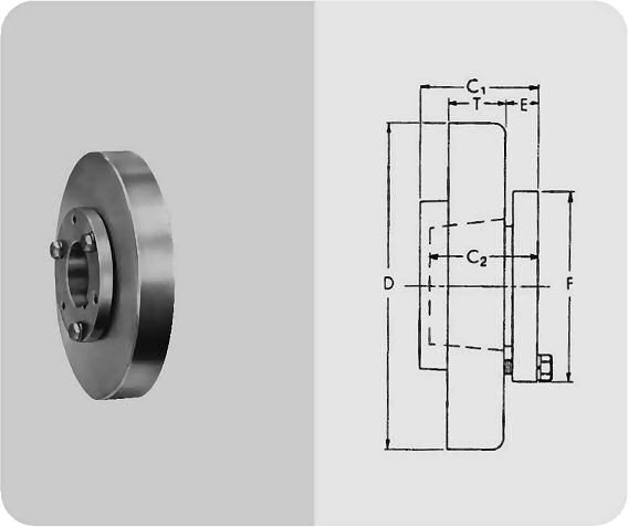
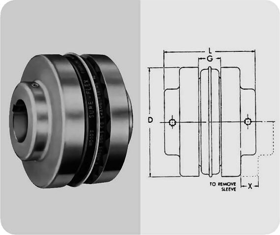
Type B flanges are made of high-strength cast iron the same as Types S, C and SC Sure-Flex flanges. Type B, however, is designed to accommodate Wood's Sure-Grip Bushing for easy installation and removal.
Sure-Grip Bushings offer convenient mounting of the flange 10 the shaft securely without setscrews. They are tapered and are split Through both the bushing flange and taper to provide a clamp fit, eliminating wobble, vibration and fretting corrosion. This is the same bushing used in Wood's sheaves and pulleys and is readily available everywhere.
| Product No. | Bushing Required | Dimensions | Max.* Bore | Range | Weight (lbs.) ■ Bushing | ||||||||
|---|---|---|---|---|---|---|---|---|---|---|---|---|---|
| C1 | C2 | D | E | F | G | L | T | X | |||||
| 6B | JA | 17⁄32 | 1 | 4.000 | 15⁄32 | 2 | 7⁄8 | 33⁄8 | 25⁄32 | 13⁄32 | 11⁄4 | 1.4 | .8 |
| 7B | JA | 15⁄8 | 1 | 4.625 | 15⁄32 | 2 | 1 | 31⁄2 | 25⁄32 | 15⁄16 | 11⁄4 | 1.9 | .8 |
| 8B | SH | 129⁄32 | 11⁄4 | 5.450 | 9⁄16 | 211⁄16 | 11⁄8 | 41⁄16 | 29⁄32 | 11⁄2 | 15⁄8 | 2.9 | 1.0 |
| 9B | SD | 21⁄4 | 113⁄16 | 6.350 | 5⁄8 | 33⁄16 | 17⁄16 | 43⁄4 | 11⁄32 | 13⁄4 | 115⁄16 | 4.8 | 1.5 |
| 10B | SK | 115⁄16 | 17⁄8 | 7.500 | 23⁄32 | 37⁄8 | 15⁄8 | 51⁄2 | 17⁄32 | 2 | 21⁄2 | 7.8 | 2.0 |
| 11B | SF | 23⁄16 | 2 | 8.625 | 11⁄16 | 45⁄8 | 17⁄8 | 61⁄4 | 11⁄2 | 23⁄8 | 215⁄16 | 12.0 | 3.5 |
| 12B | E | 223⁄32 | 25⁄8 | 10.000 | 29⁄32 | 6 | 25⁄16 | 71⁄2 | 111⁄16 | 211⁄16 | 31⁄2 | 18.0 | 9.0 |
| 13B | F | 33⁄4 | 35⁄8 | 11.750 | 11⁄16 | 65⁄8 | 211⁄16 | 83⁄4 | 131⁄32 | 3 | 315⁄16 | 31.2 | 14.0 |
| 14B | F | 33⁄4 | 35⁄8 | 13.875 | 11⁄16 | 65⁄8 | 31⁄4 | 97⁄8 | 21⁄4 | 31⁄2 | 315⁄16 | 51.4 | 14.0 |
| 16B | J | 413⁄16 | 41⁄2 | 18.875 | 11⁄4 | 71⁄4 | 43⁄4 | 123⁄4 | 23⁄4 | 41⁄4 | 41⁄2 | 120.0 | 22.0 |
*Maximum bore with keyseat. ■ Approximate weight for each flange.
Type B Sure-Flex Couplings are normally supplied with the two-piece E sleeve, and can use any EPDM or Neoprene sleeves. DO NOT use Hytrel sleeves with Type B couplings.
Spacing between internal flange hubs equals L minus 2 times C. Spacing between shafts should be greater than 118 in. and less than G.
| Bushing | Bores | Keyseat |
|---|---|---|
| JA | 1⁄2 - 1 | Standard ② |
| 11⁄16 - 13⁄16 | 1⁄4 x 1⁄16 | |
| 11⁄4 | 1⁄4 x 1⁄32 | |
| SH | 1⁄2 - 13⁄8 | Standard ② |
| 17⁄16 - 15⁄8 | 3⁄8 x 1⁄16 | |
| 111⁄16 | No K.S. | |
| SD | 1⁄2 - 111⁄16 | Standard ② |
| 13⁄4 | 3⁄8 x 1⁄8 | |
| 113⁄16 | 1⁄2 x 1⁄8 | |
| 17⁄8 - 115⁄16 | 1⁄2 x 1⁄16 | |
| 2 | No K.S. | |
| SK | 1⁄2 - 21⁄8 | Standard ② |
| 23⁄16 - 21⁄4 | 1⁄2 x 1⁄8 | |
| 25⁄16 - 21⁄2 | 5⁄8 x 1⁄16 | |
| 29⁄16 - 25⁄8 | No K.S. |
| Bushing | Bores | Keyseat |
|---|---|---|
| SF | 1⁄2 - 21⁄4 | Standard ② |
| 25⁄16 - 21⁄2 | 5⁄8 x 3⁄16 | |
| 29⁄16 - 23⁄4 | 5⁄8 x 1⁄16 | |
| 213⁄16 - 27⁄8 | 3⁄4 x 1⁄16 | |
| 215⁄16 | 3⁄4 x 1⁄32 | |
| E | 7⁄8 - 27⁄8 | Standard ② |
| 215⁄16 - 31⁄4 | 3⁄4 x 1⁄8 | |
| 35⁄16 - 31⁄2 | 7⁄8 x 1⁄16 | |
| F | 1 - 31⁄4 | Standard ② |
| 35⁄16 - 33⁄4 | 7⁄8 x 3⁄16 | |
| 313⁄16 - 315⁄16 | 1 x 1⁄8 | |
| 4 | NO K.S. | |
| J | 17⁄16 - 313⁄16 | Standard ② |
| 37⁄8 - 315⁄16 | 1 x 3⁄8 | |
| 4 - 41⁄2 | 1 x 1⁄8 |
| Shaft Dia. | Width | Depth |
|---|---|---|
| 1⁄2 - 9⁄16 | 1⁄8 | 1⁄16 |
| 5⁄8 x 7⁄8; | 3⁄16 | 3⁄32 |
| 15⁄16 x 11⁄4 | 1⁄4 | 1⁄8 |
| 15⁄16 x 13⁄8 | 5⁄16 | 5⁄32 |
| 17⁄16 x 13⁄4 | 3⁄8 | 3⁄16 |
| 113⁄16 x 21⁄4 | 1⁄2 | 1⁄4 |
| 25⁄16 x 23⁄4 | 5⁄8 | 5⁄16 |
| 213⁄16 x 31⁄4 | 3⁄4 | 3⁄8 |
| 35⁄16 x 33⁄4 | 7⁄8 | 7⁄16 |
| 313⁄16 x 41⁄2 | 1 | 1⁄2 |
| 49⁄16 x 51⁄2 | 11⁄4 | 5⁄8 |
| 59⁄16 x 61⁄2 | 11⁄2 | 3⁄4 |
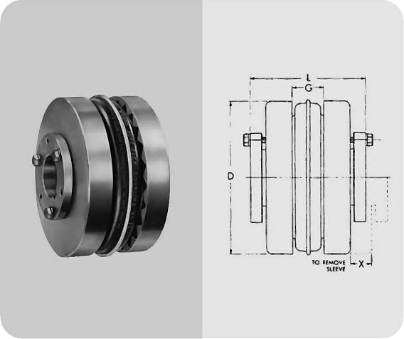
The table below shows assembled dimensions of Sure-Flex Type SC Spacer Couplings.
| Coupling Size | Required Distance Between Shafts | Use Flange No. | Use Hub No. | Max. Bore Std. KS | Dimensions | Wt. (lbs.) ■ | |||
|---|---|---|---|---|---|---|---|---|---|
| D | L(2) | G | R | ||||||
| 4JSC | 3-1⁄2 | 4JSC35 | 1-1⁄8 (1) | 2.460 | 5-5⁄8 | 5⁄8 | 2.7 | ||
| 5SC | 3-1⁄2 | 5SC35 | 5SCH | 1-1⁄8 | 3.250 | 5-5⁄8 | 3⁄4 | 9⁄16 | 4.5 |
| 6SC | 3-1⁄2 | 6SC35 | 6SCH-6SCHS | 1-3⁄8 | 4.000 | 5-7⁄8 | 7⁄8 | 3⁄4 | 7.3 |
| 4-3⁄8 | 6SC44 | 6SCH-6SCHS | 1-3⁄8 | 4.000 | 6-3⁄4 | 7⁄8 | 3⁄4 | 8.1 | |
| 5 | 6SC50 | 6SCH-6SCHS | 1-3⁄8 | 4.000 | 7-3⁄8 | 7⁄8 | 3⁄4 | 8.7 | |
| 7SC | 3-1⁄2 | 7SC35 | 7SCH-7SCHS | 1-5⁄8 | 4.625 | 6-3⁄8 | 1 | 5⁄8 | 9.9 |
| 4-3⁄8 | 7SC44 | 7SCH-7SCHS | 1-5⁄8 | 4.625 | 7-1⁄4 | 1 | 5⁄8 | 10.8 | |
| 5 | 7SC50 | 7SCH-7SCHS | 1-5⁄8 | 4.625 | 7-7⁄8 | 1 | 5⁄8 | 11.4 | |
| 8SC | 3-1⁄2 | 8SC35 | 8SCH-8SCHS | 1-7⁄8 | 5.450 | 6-7⁄8 | 1-1⁄8 | 13⁄16 | 15.2 |
| 8SC35-10 | 10SCH-10SCHS | 2-3⁄8 | 5.450 | 8-1⁄8 | 1-1⁄8 | 13⁄16 | 23.2 | ||
| 4-3⁄8 | 8SC44 | 8SCH-8SCHS | 1-7⁄8 | 5.450 | 7-3⁄4 | 1-1⁄8 | 13⁄16 | 16.4 | |
| 5 | 8SC50 | 8SCH-8SCHS | 1-7⁄8 | 5.450 | 8-3⁄8 | 1-1⁄8 | 1-3⁄16 | 17.4 | |
| 8SC50-10 | 10SCH-10SCHS | 2-3⁄8 | 5.450 | 9-5⁄8 | 1-1⁄8 | 1-3⁄16 | 27.2 | ||
| 9SC | 3-1⁄2 | 9SC35 | 9SCH-9SCHS | 2-1⁄8 | 6.350 | 7-1⁄2 | 1-7⁄16 | 1-1⁄16 | 18.6 |
| 4-3⁄8 | 9SC44 | 9SCH-9SCHS | 2-1⁄8 | 6.350 | 8-1⁄4 | 1-7⁄16 | 1-1⁄16 | 22.2 | |
| 5 | 9SC50 | 9SCH-9SCHS | 2-1⁄8 | 6.350 | 8-7⁄8 | 1-7⁄16 | 1-1⁄16 | 23.2 | |
| 9SC50-11 | 11SCH-11SCHS | 2-7⁄8 | 6.350 | 10-3⁄8 | 1-7⁄16 | 1-3⁄16 | 40.4 | ||
| 7 | 9SC70-11 | 11SCH-11SCHS | 2-7⁄8 | 6.350 | 12-3⁄8 | 1-7⁄16 | 1-3⁄16 | 48.2 | |
| 7-3⁄4 | 9SC78-11 | 11SCH-11SCHS | 2-7⁄8 | 6.350 | 13-1⁄8 | 1-7⁄16 | 1-3⁄16 | 51.0 | |
| Coupling Size | Required Distance Between Shafts | Use Flange No. | Use Hub No. | Max. Bore Std. KS | Dimensions | Wt. (lbs.) ■ | |||
|---|---|---|---|---|---|---|---|---|---|
| D | L(2) | G | R | ||||||
| 10SC | 4-3⁄4 | 10SC48 | 10SCH-10SCHS | 2-3⁄8 | 7.500 | 9-3⁄8 | 1-5⁄8 | 1-3⁄16 | 37.6 |
| 5 | 10SC50 | 10SCH-10SCHS | 2-3⁄8 | 7.500 | 9-5⁄8 | 1-5⁄8 | 1-3⁄16 | 38.4 | |
| 7 | 10SC70-13 | 13SCH-13SCHS | 3-3⁄8 | 7.500 | 13-5⁄8 | 1-5⁄8 | 1-7⁄8 | 72.0 | |
| 7-3⁄4 | 10SC78-13 | 13SCH-13SCHS | 3-3⁄8 | 7.500 | 14-3⁄8 | 1-5⁄8 | 1-7⁄8 | 76.0 | |
| 10 | 10SC100-13 | 13SCH-13SCHS | 3-3⁄8 | 7.500 | 16-5⁄8 | 1-5⁄8 | 1-7⁄8 | 88.0 | |
| 11SC | 4-3⁄4 | 11SC48 | 11SCH-11SCHS | 2-7⁄8 | 8.625 | 10-5/16 | 1-7⁄8 | 1-3⁄16 | 54.5 |
| 5 | 11SC50 | 11SCH-11SCHS | 2-7⁄8 | 8.625 | 10-3⁄8 | 1-7⁄8 | 1-3⁄16 | 54.7 | |
| 7 | 11SC70-14 | 14SCH | 3-7⁄8 | 8.625 | 14-5⁄8 | 1-7⁄8 | 2 | 86.1 | |
| 7-3⁄4 | 11SC78-14 | 14SCH | 3-7⁄8 | 8.625 | 15-3⁄8 | 1-7⁄8 | 2 | 90.3 | |
| 10 | 11SC100-14 | 14SCH | 3-7⁄8 | 8.625 | 17-5⁄8 | 1-7⁄8 | 2 | 102.7 | |
| 12SC | 7 | 12SC70 | 12SCH-12SCHS | 2-7⁄8 | 10.000 | 12-7⁄8 | 2-5⁄16 | 1-1⁄2 | 88.1 |
| 12SC70-14 | 14SCH | 3-7⁄8 | 10.000 | 14-5⁄8 | 2-5⁄16 | 2 | 99.1 | ||
| 7-3⁄4 | 12SC78 | 12SCH-12SCHS | 2-7⁄8 | 10.000 | 13-5⁄8 | 2-5⁄16 | 1-1⁄2 | 91.9 | |
| 12SC78-14 | 14SCH | 3-7⁄8 | 10.000 | 15-3⁄8 | 2-5⁄16 | 2 | 103.3 | ||
| 10 | 12SC100-14 | 14SCH | 3-7⁄8 | 10.000 | 17-5⁄8 | 2-5⁄16 | 2 | 115.7 | |
| 13SC | 7-3⁄4 | 13SC78 | 13SCH-13SCHS | 3-3⁄8 | 11.750 | 14-3⁄8 | 2-11⁄16 | 1-7⁄8 | 129.6 |
| 14SC | 7-3⁄4 | 14SC78 | 14SCH | 3-7⁄8 | 13.875 | 15-3⁄8 | 3-1⁄4 | 2 | 179.9 |
■ Approximate weight for completely assembled spacer coupling.
(1) 4JSC35 x 1-1⁄8 has shallow keyseat. (2) "L" dimension and weight will change if one or two short (HS) hubs used. Note: specify components separately.
| Coupling Size | Flange No. | For Distance Between Shafts* | For Hub | Dimensions | Wt. (lbs.) ■ | ||||
|---|---|---|---|---|---|---|---|---|---|
| D | E | H | L | T | |||||
| 4JSC | 4JSC35 | 3-1⁄8 | 2.460 | 2-1⁄16 | 2 | 2-1⁄2 | 7⁄16 | 1.3 | |
| SSC | SSC35 | 3-1⁄2 | 5SCH | 3250 | 51⁄64 | 2 | 1-11⁄16 | 19⁄32 | 0.3 |
| 6SC | 6SC35 | 3-1⁄2 | 6SCH-6SCHS | 4.000 | 19⁄32 | 2-1⁄2 | 1-5⁄8 | 23⁄32 | 2.0 |
| 6SC44 | 4-3⁄8 | 6SCH-6SCHS | 4.000 | 1-1⁄32 | 2-1⁄2 | 2-1⁄16 | 23⁄32 | 2.4 | |
| 6SC50 | 5 | 6SCH-6SCHS | 4.000 | 1-11⁄32 | 2-1⁄2 | 2-3⁄8 | 23⁄32 | 2.7 | |
| 7SC | 7SC35 | 3-1⁄2 | 7SCH-7SCHS | 4.625 | 15⁄32 | 2-13⁄16 | 1-5⁄8 | 25⁄32 | 2.5 |
| 7SC44 | 4-3⁄8 | 7SCH-7SCHS | 4.625 | 29⁄32 | 2-13⁄16 | 2-1⁄16 | 25⁄32 | 3.0 | |
| 7SC50 | 5 | 7SCH-7SCHS | 4.625 | 1-7⁄32 | 2-13⁄16 | 2-3⁄8 | 25⁄32 | 3.3 | |
| 5SC | 8SC35 | 3-1⁄2 | 8SCH-8SCHS | 5.450 | 9⁄32 | 3-1⁄4 | 1-5⁄8 | 29⁄32 | 3.7 |
| 8SC35-10 | 3-1⁄2 | 10SCHS | 5.450 | 9⁄32 | 4-3⁄8 | 1-5⁄8 | 29⁄32 | 3.5 | |
| 8SC44 | 4-3⁄8 | 8SCH-8SCHS | 5.450 | 23⁄32 | 3-1⁄4 | 2-1⁄16 | 29⁄32 | 4.3 | |
| 8SC50 | 5 | 8SCH-8SCHS | 5.450 | 1-1⁄32 | 3-1⁄4 | 2-3⁄8 | 29⁄32 | 4.8 | |
| 8SC50-10 | 5 | 10SCH-10SCHS | 5.450 | 1-1⁄32 | 4-3⁄8 | 2-3⁄8 | 29⁄32 | 5.5 | |
| 9SC | 9SC35 | 3-1⁄2 | 9SCH-9SCHS | 6.350 | 1⁄16 | 3-5⁄8 | 1-11⁄16 | 1-1⁄32 | 4.1 |
| 9SC44 | 4-3⁄8 | 9SCH-9SCHS | 6.350 | 7⁄16 | 3-5⁄8 | 2-1⁄16 | 1-1⁄32 | 5.9 | |
| 9SC50 | 5 | 9SCH-9SCHS | 6.350 | 3⁄4 | 3-5⁄8 | 2-3⁄8 | 1-1⁄32 | 6.4 | |
| 9SC50-11 | 5 | 11SCH-11SCHS | 6.350 | 3⁄4 | 5-1⁄4 | 2-3⁄8 | 1-1⁄32 | 7.0 | |
| 9SC70-11 | 7 | 11SCH-11SCHS | 6.350 | 1-3⁄4 | 5-1⁄4 | 3-3⁄8 | 1-1⁄32 | 10.9 | |
| 9SC78-11 | 7-3⁄4 | 11SCH-11SCHS | 6.350 | 2-1⁄8 | 5-1⁄4 | 3-3⁄4 | 1-1⁄32 | 12.3 | |
| Coupling Size | Flange No. | For Distance Between Shafts* | For Hub | Dimensions | Wt. (lbs.) ■ | ||||
|---|---|---|---|---|---|---|---|---|---|
| D | E | H | L | T | |||||
| 10SC | 10SC48 | 4-3⁄4 | 10SCH-10SCHS | 7.500 | 11⁄32 | 4-3⁄8 | 2-1⁄4 | 1-7⁄32 | 9.8 |
| 10SC50 | 5 | 10SCH-10SCHS | 7.500 | 15⁄32 | 4-3⁄8 | 2-3⁄8 | 1-7⁄32 | 10.2 | |
| 10SC70-13 | 7 | 13SCH-13SCHS | 7.500 | 1-15⁄32 | 6-1⁄8 | 3-3⁄8 | 1-7⁄32 | 14.5 | |
| 10SC78-13 | 7-3⁄4 | 13SCH-13SCHS | 7.500 | 1-27⁄32 | 6-1⁄8 | 3-3⁄4 | 1-7⁄32 | 16.5 | |
| 10SC100-13 | 10 | 13SCH-13SCHS | 7.500 | 2-31⁄32 | 6-1⁄8 | 4-7⁄8 | 1-7⁄32 | 22.5 | |
| 11SC | 11SC48 | 4-3⁄4 | 11SCH-11SCHS | 8.625 | 1⁄32 | 5-1⁄4 | 1-1⁄2 | 1-1⁄2 | 12.5 |
| 11SC50 | 5 | 11SCH-11SCHS | 8.625 | 1⁄16 | 5-1⁄4 | 1-9⁄16 | 1-1⁄2 | 12.6 | |
| 11SC70-14 | 7 | 14SCH | 8.625 | 1-1⁄16 | 6-1⁄2 | 2-9⁄16 | 1-1⁄2 | 16.3 | |
| 11SC78-14 | 7-3⁄4 | 14SCH | 8.625 | 1⁄16 | 6-1⁄2 | 2-15⁄16 | 1-1⁄2 | 18.4 | |
| 11SC100-14 | 10 | 14SCH | 8.625 | 2⁄16 | 6-1⁄2 | 4-1⁄16 | 1-1⁄2 | 24.6 | |
| 12SC | 12SC70 | 7 | 12SCH-12SCHS | 10.000 | 21⁄32 | 5-3⁄4 | 2-15⁄32 | 1-11⁄16 | 23.4 |
| 12SC70-14 | 7 | 14SCH | 10.000 | 21⁄32 | 6-1⁄2 | 2-15⁄32 | 1-11⁄16 | 21.3 | |
| 12SC78 | 7-3⁄4 | 12SCH-12SCHS | 10.000 | 1-1⁄32 | 5-3⁄4 | 2-27⁄32 | 1-11⁄16 | 25.3 | |
| 12SC78-14 | 7-3⁄4 | 14SCH | 10.000 | 1-1⁄32 | 6-1⁄2 | 2-27⁄32 | 1-11⁄16 | 23.4 | |
| 12SC100-14 | 10 | 14SCH | 10.000 | 2-5⁄32 | 6-1⁄2 | 3-31⁄32 | 1-11⁄16 | 29.6 | |
| 13SC | 13SC78 | 7-3⁄4 | 13SCH-13SCHS | 11.750 | 9⁄16 | 6-1⁄8 | 3-1⁄4 | 1-31⁄32 | 38.4 |
| 14SC | 14SC78 | 7-3⁄4 | 14SCH | 13.875 | 1⁄32 | 6-1⁄2 | 2-23⁄32 | 2-1⁄4 | 55.2 |
* Flanges can be mixed to form different Between-Shaft Dimensions. ■ Approximate weight for each flange. ▲ If using 10HS hub, 7⁄16-14NC x 2-1⁄4 long capscrew needed (not furnished).
| Coupling Size | Hub No. | Max. Bore | STOCK BORES* | Dimensions | Wt. (lbs.) ■ | |||
|---|---|---|---|---|---|---|---|---|
| Plain Bore | Bore with Standard Keyway & Set Screw | C | H | Cap Screws Furnished | ||||
| 4JSC | ✝ | 1-1⁄8 | 5⁄8 - 7⁄8 - 1 -1-1⁄8* | 1-1⁄16 | 2 | |||
| 5SC | SSCH | 1-1⁄8 | 1⁄3 | 5⁄8 - 3⁄4 - 7⁄8 - 1 - 1-1⁄8 | 1-3⁄32 | 2 | 4-10 x 1-1⁄3 | 0.8 |
| 6SC | 6SCH | 1-3⁄8 | 5⁄8 | 3⁄4 - 7⁄8 - 1 - 1-1⁄8 - 1-1⁄4 - 1-3⁄8 | 1-7⁄32 | 2-1⁄3 | 4-1⁄4 x 1-3⁄4 | 1.4 |
| 6SCHS | 7⁄8 | 7⁄8 | 31⁄32 | 2-1⁄3 | 4-1⁄4 x 1-1⁄3 | 1.1 | ||
| 7SC | 7SCH | 1-5⁄8 | 5⁄8 | 7⁄8 - 1 - 1-1⁄8 - 1-3⁄8 - 1-1⁄3 - 1-5⁄8 | 1-15⁄32 | 2-13⁄16 | 4-1⁄4 x 1-7⁄8 | 2.0 |
| 7SCHS | 7⁄8 | 7⁄8 | 1-3⁄32 | 2-13⁄16 | 4-1⁄4 x 1-1⁄3 | 1.5 | ||
| 8SC | 8SCH | 1-7⁄8 | 3⁄4 | 7⁄8 - 1 - 1-1⁄8 - 1-3⁄8 - 1-1⁄3 - 1-5⁄8 - 1-3⁄4 - 1-7⁄8 | 1-23⁄32 | 3-1⁄4 | 4-5⁄16 x 2-1⁄4 | 3.2 |
| 8SCHS | 7⁄8 | 7⁄8 | 1-7⁄32 | 3-1⁄4 | 4-5⁄16 x 1-3⁄4 | 2.0 | ||
| 9SC | 9SCH | 2-1⁄8 | 7⁄8 | 1 - 1-1⁄8 - 1-3⁄8 - 1-1⁄3 - 1-5⁄8 - 1-3⁄4 - 1-7⁄8 - 2-1⁄8 | 1-31⁄32 | 3-5⁄8 | 4-3⁄8 x 2-3⁄4 | 4.2 |
| 9SCHS | 1-1⁄3 | 1-1⁄8 | 1-17⁄32 | 3-5⁄8 | 4-3⁄8 x 2-1⁄4 | 3.7 | ||
| 10SC | 10SCH | 2-3⁄8 | 1-1⁄8 | 1-5⁄8 - 1-7⁄8 - 2-1⁄8 - 2-3⁄8 | 2-11⁄32 | 4-3⁄8 | 4-7⁄16 x 3-1⁄4 | 7.4 |
| 10SCHS | 1-5⁄8 | 1-1⁄8 | 1-21⁄32 | 4-3⁄8 | 4-7⁄16 x 2-1⁄3 | 5.5 | ||
| 11SC | 11SCH | 2-7⁄8 | 1-1⁄8 | 1-7⁄8 - 2-1⁄8 - 2-3⁄8 - 2-7⁄8 | 2-23⁄32 | 5-1⁄4 | 4-1⁄3 x 3-1⁄3 | 12.2 |
| 11SCHS | 1-7⁄8 | 1-1⁄8 - 1-5⁄8 | 1-29⁄32 | 5-1⁄4 | 4-1⁄3 x 2-3⁄4 | 9.3 | ||
| 12SC | 12SCH | 2-7⁄8 | 1-3⁄8 | 2-1⁄8 - 2-3⁄8 - 2-7⁄8 | 2-31⁄32 | 5-3⁄4 | 4-5⁄8 x 4 | 16.6 |
| 12SCHS | 2-1⁄3 | 2-3⁄8 | 2-17⁄32 | 5-3⁄4 | 4-5⁄8 x 3-1⁄3 | 14.1 | ||
| 13SC | 13SCH | 3-3⁄8 | 1-3⁄8 | 2-3⁄8 - 2-7⁄8 - 3-3⁄8 | 3-11⁄32 | 6-1⁄8 | 4-5⁄8 x 4-1⁄3 | 19.9 |
| 13SCHS | 2-1⁄3 | 2-1⁄8 - 2-3⁄8 | 2-15⁄32 | 6-1⁄8 | 4-5⁄8 x 3-1⁄3 | 16.0 | ||
| 14SC | 14SCH | 3-7⁄8 | 1-5⁄8 | 2-3⁄8 - 2-7⁄8 - 3-3⁄8 - 3-7⁄8 | 3-27⁄32 | 6-1⁄3 | 4-5⁄8 x 5 | 24.2 |
✝ FOR 4JSC the hub is an integral part of the flange. 4JSC x 1-1⁄8 has 1⁄4 x 1⁄16 shallow keyseat. ■ Approximate weight for each hub.
Spacer couplings are available having the most popular between shaft dimensions. Other spacings can be achieved by mixing flanges.
The "Standard" column provides spacings using identical flanges; the "Combination" column mixes flanges; the column headed "Semi-Spacer" uses one flange that is not made for spacer coupling applications and thus does not have a detachable hub.
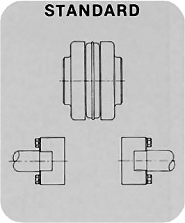
| STANDARD | |
|---|---|
| Spacing | Use Flanges* |
| 3-1⁄2 | 2-( ) SC35 |
| 4-3⁄8 | 2-( ) SC44 |
| 5 | 2-( ) SC50 |
| 7 | 2-( ) SC70 |
| 7-3⁄4 | 2-( ) SC78 |
| 10 | 2-( ) SC100 |
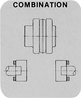
| COMBINATION | |
|---|---|
| Spacing | Use Flanges* |
| 3-15⁄16 | SC35 & SC44 |
| 4-1⁄4 | SC35 & SC50 |
| 4-11⁄16 | SC44 & SC50 |
| 5-1⁄4 | SC35 & SC70 |
| 5-5⁄8 | SC35 & SC78 |
| 5-11⁄16 | SC44 & SC70 |
| 6 | SC50 & SC70 |
| 6-1⁄16 | SC44 & SC78 |
| 6-3⁄8 | SC50 & SC78 |
| 6-3⁄4 | SC35 & SC100** |
| 7-3⁄16 | SC44 & SC100** |
| 7-3⁄8 | SC70 & SC78 |
| 7-1⁄2 | SC50 & SC100 |
| 8-1⁄2 | SC70 & SC100 |
| 8-7⁄8 | SC78 & SC100 |
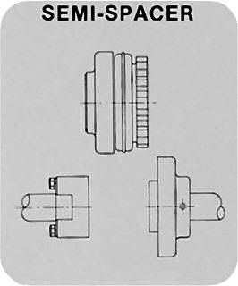
| SEMI-SPACER | |
|---|---|
| Spacing | Use Flanges* |
| 1-7⁄8 | S & SC35 |
| 2-5⁄16 | S & SC44 |
| 2-5⁄8 | S & SC50 |
| 3-5⁄8 | S & SC70 |
| 4 | S & SC78 |
| 5-1⁄8 | S & SC100 |
* Check individual coupling size for flange availability.
** Non-Stock
Note: Other combinations available - consult factory.
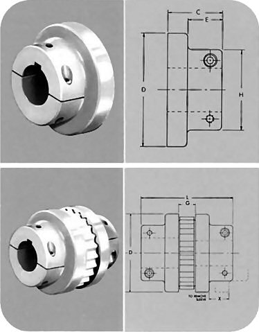
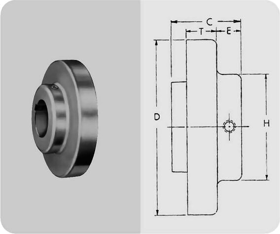
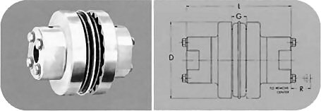
Sure-Flex. Type C Clamp Hub flanges employ integral locking collars and screws to assure a clamp fit on the shaft. One setscrew is furnished over the key. They are designed primarily for applications where flanges must be removed from one or both shafts without moving either the driver or doven units. A typical application is a screw compressor which uses a replaceable face seal around the input shaft.
Type C Clamp Hub Couplings normally use Hytrel sleeves. However, any of the sleeves shown can be used. Type C couplings may often be used where spacer couplings are required.
Spacing between internal flange hubs equals G.
| Flange Size | S k Bores | Min. Bore | Maximum Bore | Distance Between Shafts | Dimensions | Approx Wt. (lbs.)* ■ | ||||||||
|---|---|---|---|---|---|---|---|---|---|---|---|---|---|---|
| Standard Keyseat | Shallow Keyseat | Min. | Max. | C | D | E | G | H | L | X | ||||
| 6C | 1-1⁄8, 1-7⁄8, 40mm | 7⁄8 | 1-5⁄8 | 1-7⁄8 | 2 | 2-3⁄4 | 1-15⁄16 | 4.000 | 1.16 | 7⁄8 | 3 | 4-3⁄4 | 1 | 2.6 |
| 7C | 1-3⁄8, 1-7⁄8, 35mm, 40mm | 1-1⁄8 | 1-7⁄8 | - | 2-5⁄16 | 3-7⁄16 | 2-3⁄16 | 4.625 | 1.41 | 1-1⁄16 | 3-1⁄4 | 5-7⁄16 | 1-3⁄16 | 3.6 |
| 8C | 1-3⁄8, 1-5⁄8, 1-3⁄4, 1-7⁄8, 2-1⁄8, 2-1⁄4, 2-3⁄8, 40mm | 1-3⁄8 | 2-1⁄4 | 2-3⁄8 | 2-9⁄16 | 4 | 2-1⁄2 | 5.450 | 1.59 | 1-1⁄8 | 3-7⁄8 | 6-1⁄8 | 1-3⁄8 | 6.5 |
| 9C | 1-5⁄8, 1-3⁄4, 1-7⁄8, 2, 2-1⁄8, 2-1⁄4, 2-3⁄8, 2-1⁄2 | 1-5⁄8 | 2-1⁄2 | 2-11⁄16 | 3-1⁄16 | 4-5⁄8 | 3 | 6.350 | 1.97 | 1-7⁄16 | 4-1⁄4 | 7-7⁄16 | 1-9⁄16 | 9.8 |
| 10C | 1-5⁄8, 1-7⁄8, 2-1⁄4, 2-3⁄8, 2-1⁄2 | 1-5⁄8 | 2-7⁄8 | - | 3-9⁄16 | 5-1⁄4 | 3-1⁄2 | 7.500 | 2.28 | 1-11⁄16 | 5 | 8-11⁄16 | 1-13⁄16 | 16.6 |
| 11C | 2-1⁄8, 2-3⁄8, 2-1⁄2 | 1-7⁄8 | 3-3⁄8 | - | 4-1⁄8 | 5-7⁄8 | 4 | 8.625 | 2.5 | 1-7⁄8 | 5-3⁄8 | 9-7⁄8 | 2-1⁄8 | 26.0 |
| 12C | 2-1⁄8 | 1-7⁄8 | 3-3⁄8 | - | 4-7⁄8 | 6-1⁄2 | 4-3⁄8 | 10.000 | 2.69 | 2-3⁄8 | 6 | 11-1⁄8 | 2-3⁄8 | 38.3 |
* Weight of one flange.
These bores provide a slip fit.
| Bore (in.) | Tolerance (in.) |
|---|---|
| Up to and including 2" | +.0005 to +.0015 |
| Over 2" | +.0005 to +.0020 |
Some large bore Type C flanges are supplied with shallow keyseats. In these cases, a rectangular key is furnished. The flanges and bores involved are as follows:
| Size | Bore Range | KS | Key Furnished |
|---|---|---|---|
| 6C | 1-11⁄16 to 1-7⁄8 | 1⁄2 x 1⁄16 | 1⁄2 x 5⁄16 x 1-7⁄8 |
| 8C | 2-5⁄16 to 2-3⁄8 | 5⁄8 x 1⁄16 | 5⁄8 x 3⁄8 x 2-1⁄2 |
| 9C | 2-7⁄16 to 2-11⁄16 | 5⁄8 x 3⁄16 | 5⁄8 x 1⁄2 x 3 |
Sure-Flex flanges (outer metallic parts) and sleeves (inner elastomeric members) come in many sizes and types. First, determine the size and type of components being used. Remove all components from their boxes, and loosely assemble the coupling on any convenient surface. (Do not attempt to install the wire ring on the two-piece E or N sleeve at this time.) Also check maximum RPM values in the table against operating speed. All rubber sleeves (EPDM and Neoprene) have the same ratings for a given size and may be used interchangeably. However, because rubber and Hytrel sleeves have completely different ratings, they never should be used interchangeably.
Inspect all coupling components and remove any protective coatings or lubricants from bores, mating surfaces and fasteners. Remove any existing burrs, etc. from the shafts.
Slide one coupling flange onto each shaft, using snug-fitting keys where required. When using Type B flanges, follow the instructions furnished with the Sure-Grip bushing.
Position the flanges on the shafts to approximately achieve the Y dimension shown In the table. It is usually best to have an equal length of shaft extending into each flange. Move one flange to its final position. Torque fasteners to proper values. Slide the other flange far enough away to install the sleeve. With a two-piece sleeve, do not move the wire ring to its final position; allow it to hang loosely in the groove adjacent to the teeth.
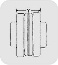
Slide the loose flange on the shaft until the sleeve is completely seated in the teeth of each flange. (The "Y" dimension is for reference and not critical.) Secure the flange to the shaft. Different coupling sleeves require different degrees of alignment precision. Locate the alignment values for your sleeve size and type in the table.
Check parallel alignment by placing a straight-edge across the two coupling flanges and measuring the maximum offset at various points around the periphery of the coupling without rotating the coupling. If the maximum offset exceeds the figure shown under "Parallel" in the table, realign the shafts.
Check angular alignment with a micrometer or caliper. Measure from the outside of one flange to the outside of the other at intervals around the periphery of the coupling.
Determine the maximum and minimum dimensions without rotating the coupling. The difference between the maximum and minimum must not exceed the figure given under "Angular" in the table. If a correction is necessary, be sure to recheck the parallel alignment.
Parallel
Angular
(Dimensions in inches)
| Sleeve Size | Maximum RPM | Types JE, IN, JES, JNS, E & N | *Type H & HS | ||||
|---|---|---|---|---|---|---|---|
| Parallel | Angular | Y | Parallel | Angular | Y | ||
| 3 | 9200 | .010 | .035 | 1.188 | |||
| 4 | 7600 | .010 | .043 | 1.500 | |||
| 5 | 7600 | .015 | .056 | 1.938 | |||
| 6 | 6000 | .015 | .070 | 2.375 | .010 | .016 | 2.375 |
| 7 | 5250 | .020 | .081 | 2.563 | .012 | .020 | 2.563 |
| 8 | 4500 | .020 | .094 | 2.938 | .015 | .025 | 2.938 |
| 9 | 3750 | .025 | .109 | 3.500 | .017 | .028 | 3.500 |
| 10 | 3600 | .025 | .128 | 4.063 | .020 | .032 | 4.063 |
| 11 | 3600 | .032 | .151 | 4.875 | .022 | .037 | 4.875 |
| 12 | 2800 | .032 | .175 | 4.688 | .025 | .042 | 5.688 |
| 13 | 2400 | .040 | .195 | 6.688 | .030 | .050 | 6.625 |
| 14 | 2200 | .045 | .242 | 7.750 | .035 | .060 | 7.750 |
| 16 | 1500 | .062 | .330 | 10.250 | |||
Note: Values shown above apply if the actual torque transmitted is more than ¼ the coupling rating. For lesser torque, reduce the above values by ½.
*Type H and HS sleeves should not be used as direct replacements for EPDM or Neoprene sleeves.
If the coupling employs the two-piece sleeve with the wire ring, force the ring into its groove in the center of the sleeve. It may be necessary to pry the ring into position with a blunt screwdriver.
Install coupling guards per OSHA requirements.
CAUTION: Coupling sleeves may be thrown from the coupling assembly with substantial force when the coupling is subjected to a severe shock load or abuse.
"ABSSAC" is a registered trade mark 2375859
All rights are reserved.
The use of this catalogue is made available to you by Abssac Limited. The exclusive right to control the use of the copyright and trademarks on this site is controlled by Abssac Limited. These may not be copied, reproduced, published, distributed, modified or otherwise used in any form including electronic copying without the express permission of Abssac Limited. Abssac Limited has made all reasonable endeavor to ensure that the material on this site is accurate. You agree that Abssac Limited, nor any other person involved in creating or providing this catalogue shall be liable for any indirect or consequential damage arising from the use of any information contained in this catalogue.
The information contained in this catalogue is provided 'as is' without warranty of any kind, either expressed or implied. Abssac Limited assumes no responsibility for errors or omissions in this catalogue or other documents which are reference by or linked to this catalogue. This catalogue could include technical or other inaccuracies including typographical errors. Updates and changes are periodically added to the information herein; these changes will be incorporated in new editions of this catalogue. Abssac Limited may make improvements and/or changes in the product(s) or service(s) described in this publication at any time. You agree that the above terms represent the entire basis of the agreement between us, upon which you are permitted to enter this site and you agree that all relations between us are subject to the Law of England and Wales.