![]()
Considerable savings when compared to ball screw assemblies.
Large range of leads and diameters to match your requirements.
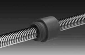
Internally lubricated plastic nuts will operate without additional lubrication. However, TriGEL grease or dry film lubricant is recommended and will extend product life. See pages 13 and 14.
No ball recirculation vibration and often less audible noise compared to ball screws.
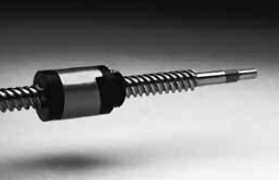
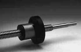
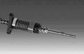
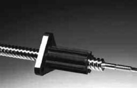
Supernuts provide a cost effective solution for moderate to light loads. For vertical applications, anti-backlash supernuts should be mounted with thread/flange on the bottom.
Cantilevered loads that might cause a moment on the nut will cause premature failure.
Refer to critical speed chart.
Refer to column loading chart.
Lead screws can be self locking at low leads. Generally, the lead of the screw should be more than 1/3 of the diameter to satisfactorily backdrive.
Option of custom components to fit into your design envelope.
Stainless Steel and internally lubricated acetal.
Less susceptible to particulate contamination compared to ball screws.
Less mass to move.
Ambient and friction generated heat are the primary causes of premature plastic nut failure. Observe the temperature limits below and discuss your design with our application engineers for continuous duty, high load and high speed applications. Danaher Motion recommends bronze nuts for very high temperature environments or can aid in your selection of high temperature plastic for a custom assembly.
Except at very high leads, efficiency increases as lead increases. Although the internally lubricated acetal provides excellent lubricity, Ball Screw Assemblies remain significantly more efficient than most Lead Screw designs.
| Assembly | Screws | Nuts** | ||||
|---|---|---|---|---|---|---|
| Maximum Temperature | Friction Coefficient | Material | Material | Tensile Strength | Water Absorption (24 HRS %) | Thermal Expansion Coefficient |
| 82°C | 0,08 - 0,14 | Stainless Steel* | Acetal with PTFE | 55 MPa | 0,15 | 9,7 x 10⁻⁵ m/m/°C |
* 1.4301 (AISI 304) & 1.4305 (AISI 303) ** Other materials available on a custom basis.
Driving the screw to translate the nut, or driving the nut to translate the screw.
Torque
(N-mm)=Load (N) × Lead (mm)
2π × efficiency
Loading the nut to rotate the screw
Torque=Load × Lead × Efficiency
2π
% Efficiency= tan (helix angle)
tan (helix angle + arctan f)× 100
As a rule, assemblies that have an efficiency of 50% or more will backdrive.
See page 12 for efficiencies. Efficiencies listed in catalogue computed at 0,1 friction coefficient.
| Series | Precision Lead Screw |
|---|---|
| Lead accuracy | Standard - 250 ìm / 300 mm Precision -75 ìm / 300 mm |
| Diameter | 10 to 24 mm |
| Lead | 2 to 45 mm |
| Backlash | ,02 to ,25 mm (standard nut) Zero backlash available |
| Dynamic Load | Up to 1550 N |
| Max. Static Load | Up to 6675 N |
| Catalogue Pages | 10 to 12 |
Metric | Lead (mm) | |||||||||||||
| 2 | 3 | 4 | 5 | 6 | 8 | 10 | 12 | 15 | 16 | 20 | 25 | 35 | 45 | |
|---|---|---|---|---|---|---|---|---|---|---|---|---|---|---|
| Dia. (mm) | ||||||||||||||
| 10 | • | • | • | • | • | • | • | |||||||
| 12 | • | • | • | • | • | • | • | • | ||||||
| 16 | • | • | • | • | • | • | ||||||||
| 20 | • | • | • | • | • | • | ||||||||
| 24 | • | |||||||||||||
• = stocked size
InchAlso available are our inch series lead screws.Consult our website for further details at www.abssac.co.uk | Lead (Zoll) | |||||||||||||
| 0,050 | 0,063 | 0,083 | 0,100 | 0,125 | 0,167 | 0,200 | 0,250 | 0,375 | 0,500 | 0,800 | 1,000 | 1,200 | 2,000 | |
|---|---|---|---|---|---|---|---|---|---|---|---|---|---|---|
| Dia. (in) | ||||||||||||||
| 3/8 | • | • | • | • | • | • | • | • | • | • | • | |||
| 7/16 | • | • | • | |||||||||||
| 1/2 | • | • | • | • | • | • | • | |||||||
| 5/8 | • | • | • | • | • | |||||||||
| 3/4 | • | • | • | • | • | • | • | |||||||
| 1 | • | • | • | • | • | • | ||||||||
Note: Miniature sizes also offered. Consult our website for further details at www.abssac.co.uk
Custom diameters and leads per request.
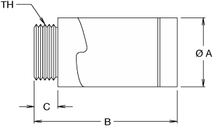
| Model # | Screw Series (mm) | Also Use w/Series (inch) | Dimensions | Design Load (N) | Drag Torque | ||||
|---|---|---|---|---|---|---|---|---|---|
| A (mm) | B (mm) max | C (mm) | TH (mm) | Minimum (N-mm) | Maximum (N-mm) | ||||
| AB3700 | 10 | 5/16, 3/8 | 20,8 | 47,6 | 6,4 | M16 x 1,5 | 100 | 7 | 21 |
| AB5000 | 12 | 7/16, 1/2 | 28,4 | 57,2 | 9,5 | M25 x 1,5 | 550 | 7 | 21 |
| AB6200 | 16 | 5/8 | 35,6 | 66,0 | 12,7 | M30 x 1,5 | 775 | 14 | 42 |
| AB7500 | 20 | 3/4 | 41,4 | 73,7 | 12,7 | M35 x 1,5 | 1100 | 21 | 71 |
| AB10000 | 24 | 1 | 47,8 | 76,2 | 15,2 | M40 x 1,5 | 1550 | 35 | 71 |
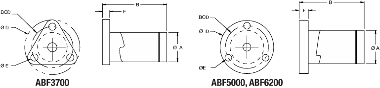
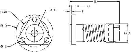
| Model # | Screw Series (mm) | Also Use w/Series (inch) | Dimensions | Design Load (N) | Drag Torque | ||||||
|---|---|---|---|---|---|---|---|---|---|---|---|
| A (mm) | B (mm) max | D (mm) | E (mm) | F (mm) | BCD (mm) | Minimum (N-mm) | Maximum (N-mm) | ||||
| ABF3700 | 10 | 5/16, 3/8 | 20,8 | 47,6 | 38,1 | 5,1 | 5,1 | 28,6 | 100 | 7 | 21 |
| ABF5000 | 12 | 7/16, 1/2 | 28,4 | 57,2 | 44,5 | 5,6 | 7,6 | 35,5 | 550 | 7 | 21 |
| ABF6200 | 16 | 5/8 | 35,6 | 66,0 | 54,1 | 5,6 | 12,7 | 42,9 | 775 | 14 | 42 |
| Model # | Screw Series (mm) | Also Use w/Series (inch) | Dimensions | Design Load (N) | Drag Torque | ||||||||
|---|---|---|---|---|---|---|---|---|---|---|---|---|---|
| A (mm) | B (mm) | C (mm) | D (mm) | E (mm) | F (mm) | G (mm) | BCD (mm) | Minimum (N-mm) | Maximum (N-mm) | ||||
| ABFT3700 | 10 | 3/8, 7/16 | 19,6 | 50,8 | 5,1 | 38,1 | 5,1 | 1,5 | 18,0 | 28,6 | 45 | 14 | 35 |
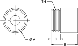
| Model # | Screw Series (mm) | Also Use w/Series (inch) | Dimensions | Design Load (N) | Max Static Load (N) | Drag Torque | |||
|---|---|---|---|---|---|---|---|---|---|
| A (mm) | B (mm) | C (mm) | TH (mm) | ||||||
| SN3700 | 10 | 5/16, 3/8 | 19,1 | 19,1 | 6,4 | M16 x 1,5 | 310 | 1550 | No Preload |
| SN5000 | 12, 16 | 7/16, 1/2 | 25,4 | 25,4 | 9,5 | M22 x 1,5 | 445 | 2225 | |
| SN1000 | 20, 24 | 3/4, 1 | 38,1 | 38,1 | 12,7 | M35 x 1,5 | 1335 | 6675 | |
| Model # | Screw Series (mm) | Also Use w/Series (inch) | Dimensions | Design Load (N) | Drag Torque | |||||
|---|---|---|---|---|---|---|---|---|---|---|
| A (mm) | B (mm) | D (mm) | E (mm) | F (mm) | BCD (mm) | |||||
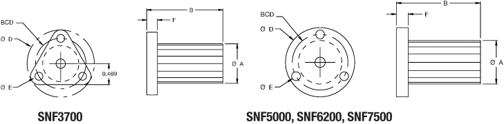
| SNF3700 | 10 | 3/8, 7/16 | 18,0 | 38,1 | 38,1 | 5,1 | 5,1 | 28,6 | 325 | No Preload |
| SNF5000 | 12 | 1/2 | 19,1 | 38,1 | 38,1 | 5,1 | 6,4 | 28,6 | 550 | |
| SNF6200 | 16 | 5/8 | 22,4 | 41,4 | 38,1 | 5,1 | 7,6 | 30,2 | 775 | |
| SNF7500 | 20 | 3/4 | 28,6 | 44,5 | 50,8 | 5,1 | 7,6 | 36,5 | 1200 | |
Note: Design load is the recommended maximum operating load with lubrication at room temperature, 50% duty cycle, and 500 RPM. Increasing the RPM will decrease the maximum allowable operating load. At 1,000 RPM, the operating load is approximately 1/2 of the rated design load.
Burnished Finish
303 Stainless Steel
 Some sizes available in 1018 Steel
| Diameter | Lead | Size | Part No. | Recommended Bearing |
|---|---|---|---|---|
| 6 mm | 1 mm | 6 x 1 | SV6x1 | 4mm |
| 1/4 " | 0.0125 | 1/4-80 | SV2580 | 4mm |
| 0.0208 | 1/4-48 | SV2548 | ||
| 0.025 | 1/4-40 | SV2540 | ||
| 0.0278 | 1/4-36 | SV2536 | ||
| 0.0313 | 1/4-32 | SV2532 | ||
| 0.0357 | 1/4-28 | SV2528 | ||
| 0.0417 | 1/4-24 | SV2524 | ||
| 0.050 | 1/4-20 | SV2520 | ||
| 3/8 " | 0.025 | 3/8-40 | SV3740 | 4 or 6mm |
| 0.0313 | 3/8-32 | SV3732 | ||
| 0.0417 | 3/8-24 | SV3724 | ||
| 0.050 | 3/8-20 | SV3720 | ||
| 0.0625 | 3/8-16 | SV3716 | ||
| 0.0833 | 3/8-12 | SV3712 | ||
| 1/2 " | 0.025 | 1/2-40 | SV5040 | 6 or 8mm |
| 0.0333 | 1/2-30 | SV5030 | ||
| 0.050 | 1/2-20 | SV5020 | ||
| 0.0625 | 1/2-16 | SV5016 | ||
| 0.0769 | 1/2-13 | SV5013 |
All dimensions in inches unless specified otherwise.
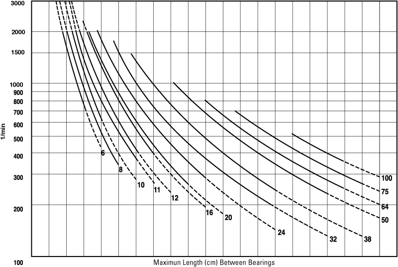
Every screw shaft has a rotational speed limit. That is the point at which the rotational speed sets up excessive vibration. This critical point is modified by the type of end bearing support used. To use this chart, determine the required RPM and the maximum length between bearing supports. Next, select one of the four types of end support shown below. The critical speed limit can be found by locating the point at which the RPM (horizontal lines) intersects with the unsupported screw length (vertical lines) as modified by the type of supports select below. We recommend operating at no more than 80% of the critical speed limit.
Warning: Curves for the screw diameters shown are based on the smallest root (minor) diameter of the standard screws within the nominal size range and truncated at the maximum ball nut rotational speed. DO NOT EXCEED this RPM regardless of screw length.
| Fixed Free | 150 | 300 | 460 | 610 | 760 | 910 | 1070 | 1220 | 1370 | 1520 | 1680 | 1830 | 1980 | 2130 | 2290 | 2440 | 2590 | 2740 | 3050 | 3200 |
|---|---|---|---|---|---|---|---|---|---|---|---|---|---|---|---|---|---|---|---|---|
| Simple Simple | 250 | 510 | 760 | 1020 | 1270 | 1520 | 1780 | 2030 | 2290 | 2540 | 2790 | 3050 | 3300 | 3560 | 3810 | 4060 | 4320 | 4570 | 4830 | 5080 |
| Fixed Simple | 300 | 610 | 910 | 1220 | 1550 | 1850 | 2160 | 2460 | 2770 | 3070 | 3380 | 3910 | 4010 | 4320 | 4620 | 4930 | 5230 | 5540 | 5840 | 6150 |
| Fixed Fixed | 380 | 760 | 1140 | 1520 | 1910 | 2290 | 2670 | 3020 | 3400 | 3780 | 4170 | 4550 | 4930 | 5310 | 5690 | 6070 | 6450 | 6830 | 7210 | 7570 |
Fixed Free 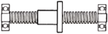
Simple Simple 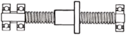
Fixed Simple 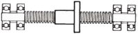
Fixed Fixed
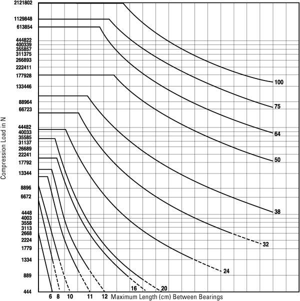
Use the chart below to determine the Maximum Compression Load for Screw Shaft. Usually, screws operated in tension can handle loads up to the rated capacity of the nut, providing the screw length is within standard lengths. End supports have an effect on the load capacity of screws. The four standard variations are shown below with corresponding rating adjustments. Find the point of intersecting lines of load (horizontal) and length (vertical) to determine the minimum safe diameter of screw. If loads fall into dotted lines, consult factory.
Warning: DO NOT EXCEED nut capacity. Curves for the screw diameters shown are based on the smallest root (minor) diameter of the standard screws within the nominal size range.
| Fixed Free | 130 | 250 | 380 | 510 | 640 | 760 | 890 | 1020 | 1140 | 1270 | 1400 | 1520 | 1650 | 1780 | 1910 | 2030 | 2160 | 2290 | 2410 |
|---|---|---|---|---|---|---|---|---|---|---|---|---|---|---|---|---|---|---|---|
| Simple Simple | 250 | 510 | 760 | 1020 | 1270 | 1520 | 1780 | 2030 | 2290 | 2540 | 2790 | 3050 | 3300 | 3560 | 3810 | 4060 | 4320 | 4570 | 4830 |
| Fixed Simple | 360 | 710 | 1070 | 1450 | 1800 | 2160 | 2510 | 2870 | 3230 | 3580 | 3960 | 4320 | 4670 | 5030 | 5380 | 5740 | 6100 | 6480 | 6860 |
| Fixed Fixed | 510 | 1020 | 1520 | 2030 | 2540 | 3050 | 3560 | 4060 | 4570 | 5080 | 5590 | 6100 | 6600 | 7110 | 7620 | 8130 | 8640 | 9140 | 9650 |
Fixed Free
Simple Simple
Fixed Simple
Fixed Fixed
Compression (Column) Load 
Tension (Pulling) Load
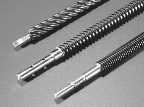
Custom nut designs are available on all screw formats.
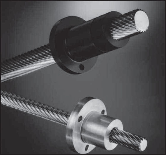
Screw leads up to 200mm can be supplied.
The revolutionary high helix lead screws can offer leads of up to 6 x the diameter of the screw. This provides high linear speeds at a low rotational speeds or effcient conversation of linear to rotary movement.
Screws can be manufactured from Steel, Stainless Steel and Aluminium whilst the associated nuts are available in wear resistant thermoplastic and Bronze for higher loads or temperature.
When choosing a High helix lead screw for your application you should consider the following:
Standard Lead Accuracy: 0.21mm / 300mm
Precision Lead Accuracy: 0.10mm / 300mm
P.O.M. (Plastic) Nuts: - 40 ° to + 60 ° C
Bronze Nuts: - 40 ° to + 200 ° C
10% at rated load with lubrication and P.O.M. nut
Lubrication intervals are dependent on application. In many cases, a single lubrication with the correct Grease or Oil will be sufficient with a P.O.M. nut. Bronze nuts require a reapplication of lubricant on a regular basis.
Basic Calculation for Max Speed depending on Load Fper = C0 . fL [ N ]
C0 = Static Load Rate [ N ]
FL = Load Factor [ - ] for P.O.M. Nut
| Circumferential Speed Vc [M / min] | Load Factor fL [ - ] |
|---|---|
| 5 | 0.95 |
| 10 | 0.75 |
| 20 | 0.45 |
| 30 | 0.37 |
| 40 | 0.12 |
| 50 | 0.08 |
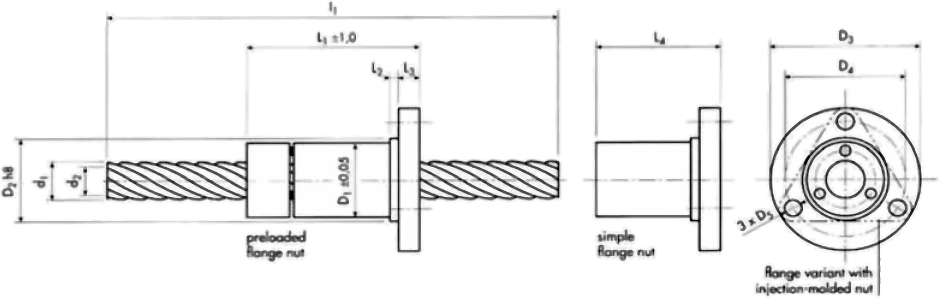
Materials Screw: Steel (including stainless) Nut: POM or Bronze
| Dimensions mm | Load Ratings Co (N) for POM | |||||||||||||
|---|---|---|---|---|---|---|---|---|---|---|---|---|---|---|
| Screw | Nut | |||||||||||||
| Do/p mm | d1 mm | d2 | p | i | D1 ±0.05 | D2 h8 | D3 | D4 | D5 | L1 POM/Bronze | L2 | L3 | L4 POM/Bronze | |
| 8/10 | 8.2 | 5.5 | 10 | 4 | 23.5 | 24 | 42 | 32 | 4.2 | 38/31 | 3 | 5 | 25/18 | 800 |
| 10/12 * | 10.0 | 7.1 | 12 | 4 | 23.5 | 24 | 42 | 32 | 4.2 | 38/31 | 3 | 5 | 25/18 | 1200 |
| 12/15 * | 12.2 | 9.2 | 15 | 5 | 23.5 | 24 | 42 | 32 | 4.2 | 38/31 | 3 | 5 | 25/18 | 1400 |
| 12/25 | 11.9 | 8.0 | 25 | 5 | 23.5 | 24 | 42 | 32 | 4.2 | 38/31 | 3 | 5 | 25/18 | 1500 |
| 10/50 * | 10.0 | 7.4 | 50 | 10 | 25.5 | 26 | 46 | 36 | 5.1 | 58/46 | 3 | 7 | 42/30 | 1250 |
| 11/60 | 11.7 | 9.1 | 60 | 12 | 25.5 | 26 | 46 | 36 | 5.1 | 58/46 | 3 | 7 | 42/30 | 1500 |
| 13/20 | 13.3 | 8.8 | 20 | 4 | 25.5 | 26 | 46 | 36 | 5.1 | 58/46 | 3 | 7 | 42/30 | 1300 |
| 13/70 | 13.5 | 10.9 | 70 | 14 | 25.5 | 26 | 46 | 36 | 5.1 | 58/46 | 3 | 7 | 42/30 | 1750 |
| 14/8 | 14.0 | 9.8 | 8 | 2 | 25.5 | 26 | 46 | 36 | 5.1 | 58/46 | 3 | 7 | 42/30 | 900 |
| 14/18 * | 14.3 | 11.4 | 8 | 6 | 25.5 | 26 | 46 | 36 | 5.1 | 58/46 | 3 | 7 | 42/30 | 1600 |
| 14/30 | 13.9 | 10.1 | 18 | 6 | 25.5 | 26 | 46 | 36 | 5.1 | 58/46 | 3 | 7 | 42/30 | 1750 |
| 15/20 | 15.2 | 12.5 | 20 | 8 | 29.5 | 30 | 49 | 39 | 5.1 | 58/46 | 3 | 7 | 42/30 | 1600 |
| 15/80 * | 15.2 | 12.6 | 80 | 16 | 29.5 | 30 | 49 | 39 | 5.1 | 58/46 | 3 | 7 | 42/30 | 2000 |
| 16/21 | 16.5 | 13.6 | 21 | 7 | 29.5 | 30 | 49 | 39 | 5.1 | 58/46 | 3 | 7 | 42/30 | 1800 |
| 16/25 | 16.0 | 11.5 | 25 | 5 | 29.5 | 30 | 49 | 39 | 5.1 | 58/46 | 3 | 7 | 42/30 | 1550 |
| 16/35 | 15.9 | 12.1 | 35 | 7 | 29.5 | 30 | 49 | 39 | 5.1 | 58/46 | 3 | 7 | 42/30 | 2000 |
| 16/90 * | 17.0 | 14.3 | 90 | 18 | 29.5 | 30 | 49 | 39 | 5.1 | 58/46 | 3 | 7 | 42/30 | 2250 |
| 18/16 | 18.0 | 14.3 | 16 | 4 | 29.5 | 30 | 49 | 39 | 5.1 | 58/46 | 3 | 7 | 42/30 | 1100 |
| 18/24 * | 18.7 | 15.7 | 24 | 8 | 29.5 | 30 | 49 | 39 | 5.1 | 58/46 | 3 | 7 | 42/30 | 2000 |
| 18/40 | 17.9 | 14.1 | 40 | 8 | 29.5 | 30 | 49 | 39 | 5.1 | 58/46 | 3 | 7 | 42/30 | 2250 |
| 18/100 * | 18.8 | 16.2 | 100 | 20 | 29.5 | 30 | 49 | 39 | 5.1 | 58/46 | 3 | 7 | 42/30 | 2500 |
| 19/30 | 18.8 | 14.2 | 30 | 6 | 29.5 | 30 | 49 | 39 | 5.1 | 58/46 | 3 | 7 | 42/30 | 1800 |
Data: Do nominal screw diameter (mm) d2 core diameter (mm) po nominal pitch (mm) p effective pitch (mm) I number of threads (-)
L1 screw length as per customer specs (mm); stock length: 3000mm
Co static load rate for non-preloaded POM nuts (N); bronze nuts must be used for higher load rates.
(load rates for bronze nuts = 1.3 x load rates of POM nuts)
* available with right-handed and left-handed thread
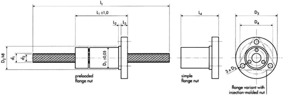
Materials Screw: Steel (including stainless) Nut: POM or Bronze
| Dimensions mm | Load Ratings Co (N) for POM | |||||||||||||
|---|---|---|---|---|---|---|---|---|---|---|---|---|---|---|
| Screw | Nut | |||||||||||||
| Do/p mm | d1 mm | d2 | p | i | D1 ±0.05 | D2 h8 | D3 | D4 | D5 | L1 POM/Bronze | L2 | L3 | L4 POM/Bronze | |
| 20/12 | 20.0 | 15.8 | 12 | 3 | 35.5 | 36 | 59 | 47 | 6.2 | 64150 | 5 | 8 | 46/32 | 1200 |
| 20/45 | 20.0 | 16.1 | 45 | 9 | 35.5 | 36 | 59 | 47 | 6.2 | 64/50 | 5 | 8 | 46/32 | 2500 |
| 21/27* | 20.8 | 17.9 | 27 | 9 | 35.5 | 36 | 59 | 47 | 6.2 | 64/50 | 5 | 8 | 46/32 | 2200 |
| 21/35 | 21.5 | 17.0 | 35 | 7 | 35.5 | 36 | 59 | 47 | 6.2 | 64/50 | 5 | 8 | 46/32 | 2050 |
| 22/20 | 22.0 | 18.3 | 20 | 5 | 35.5 | 36 | 59 | 47 | 6.2 | 64/50 | 5 | 8 | 46/32 | 1400 |
| 22/50 | 22.0 | 18.1 | 50 | 10 | 35.5 | 36 | 59 | 47 | 6.2 | 64/50 | 5 | 8 | 46/32 | 2750 |
| 23/30* | 23.0 | 20.0 | 30 | 10 | 35.5 | 36 | 59 | 47 | 6.2 | 64/50 | 5 | 8 | 46/32 | 2400 |
| 24/40 | 24.3 | 19.8 | 40 | 8 | 35.5 | 36 | 59 | 47 | 6.2 | 64/50 | 5 | 8 | 46/32 | 2300 |
| 24/55 | 24.0 | 20.1 | 55 | 11 | 35.5 | 36 | 59 | 47 | 6.2 | 64/50 | 5 | 8 | 46/32 | 3000 |
| 26/16 | 26.0 | 21.8 | 16 | 4 | 41,5 | 42 | 64 | 53 | 6.2 | 71/56 | 5 | 8 | 50/35 | 1400 |
| 26/24 | 26.0 | 22.3 | 24 | 6 | 41.5 | 42 | 64 | 53 | 6.2 | 71/56 | 5 | 8 | 50/35 | 2000 |
| 26/60 | 26.0 | 22.2 | 60 | 12 | 41.5 | 42 | 64 | 53 | 6.2 | 71/56 | 5 | 8 | 50/35 | 3250 |
| 27/45 | 27.0 | 22.5 | 45 | 9 | 41,5 | 42 | 64 | 53 | 6.2 | 71/56 | 5 | 8 | 50/35 | 2550 |
| 28/65 | 28.0 | 24.2 | 65 | 13 | 41.5 | 42 | 64 | 53 | 6.2 | 71/56 | 5 | 8 | 50/35 | 3500 |
| 30/28 | 30.0 | 26.5 | 28 | 7 | 41,5 | 42 | 64 | 53 | 6.2 | 71/56 | 5 | 8 | 50/35 | 2000 |
| 30/50 | 29.8 | 25.3 | 50 | 10 | 41,5 | 42 | 64 | 53 | 6.2 | 71/56 | 5 | 8 | 50/35 | 2800 |
| 30/70 | 30.0 | 26.2 | 70 | 14 | 41,5 | 42 | 64 | 53 | 6.2 | 71/56 | 5 | 8 | 50/35 | 3750 |
| 32/20 | 32.0 | 27.8 | 20 | 5 | 49.5 | 50 | 80 | 65 | 9.0 | -/- | 10 | 12 | 70/50 | 2000 |
| 32/75 | 32.0 | 28.2 | 75 | 15 | 49.5 | 50 | 80 | 65 | 9.0 | -/- | 10 | 12 | 70/50 | 4000 |
| 34/32 | 34.0 | 30.5 | 32 | 8 | 49.5 | 50 | 80 | 65 | 9.0 | -/- | 10 | 12 | 70/50 | 2300 |
| 34/80 | 34.0 | 30.2 | 80 | 16 | 49.5 | 50 | 80 | 65 | 9.0 | -/- | 10 | 12 | 70/50 | 4250 |
| 36/200 | 36.0 | 33.4 | 200 | 40 | 49.5 | 50 | 80 | 65 | 9.0 | -/- | 10 | 12 | 70/50 | 4500 |
Data: Do nominal screw diameter (mm) d2 core diameter (mm) po nominal pitch (mm) p effective pitch (mm) I number of threads (-)
L1 screw length as per customer specs (mm); stock length: 3000mm
Co static load rate for non-preloaded POM nuts (N); bronze nuts must be used for higher load rates.
(load rates for bronze nuts = 1.3 x load rates of POM nuts)
* available with right-handed and left-handed thread
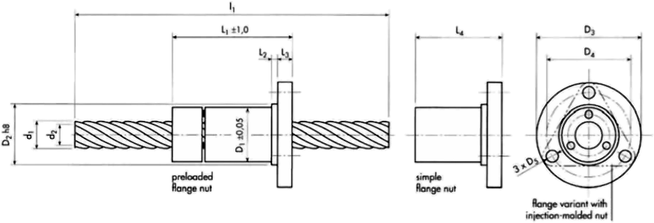
Materials
Screw: Steel (including stainless) or hard-anodised Aluminium
Nut: POM or Bronze (only with screws made of Steel)
| Dimensions mm | Load Ratings Co (N) for POM | |||||||||||||
|---|---|---|---|---|---|---|---|---|---|---|---|---|---|---|
| Screw | Nut | |||||||||||||
| Do/p mm | d1 | d2 | p | i | D1 ±0.05 | D2 h8 | D3 | D4 | D5 | L1 POM/Bronze | L2 | L3 | L4 POM/Bronze | |
| 5/5 | 5.4 | 3.6 | 5.0 | 4 | 20.5 | 21 | 38 | 29 | 4.2 | 38/31 | 3 | 5 | 25/18 | 300 |
| 5/20* | 6.0 | 5.0 | 20.0 | 16 | 20.5 | 21 | 38 | 29 | 4.2 | 38/31 | 3 | 5 | 25/18 | 300 |
| 6/25 | 7.4 | 6.3 | 25.0 | 20 | 20.5 | 21 | 38 | 29 | 4.2 | 38/31 | 3 | 5 | 25/18 | 400 |
| 7.5/7.5 | 7.7 | 5.9 | 7.5 | 6 | 20.5 | 21 | 38 | 29 | 4.2 | 38/31 | 3 | 5 | 25/18 | 450 |
| 8/30* | 8.6 | 7.5 | 30.0 | 24 | 20.5 | 21 | 38 | 29 | 4.2 | 38/31 | 3 | 5 | 25/18 | 500 |
| 10/10 | 10.0 | 8.2 | 10.0 | 8 | 23.5 | 24 | 42 | 32 | 4.2 | 38/31 | 3 | 5 | 25/18 | 600 |
| 10/35* | 10.1 | 8.9 | 35.0 | 28 | 23.5 | 24 | 42 | 32 | 4.2 | 38/31 | 3 | 5 | 25/18 | 600 |
| 11/40* | 11.5 | 10.2 | 40.0 | 32 | 23.5 | 24 | 42 | 32 | 4.2 | 38/31 | 3 | 5 | 25/18 | 700 |
| 12/45* | 12.8 | 11.4 | 45.0 | 36 | 23.5 | 24 | 42 | 32 | 4.2 | 38/31 | 3 | 5 | 25/18 | 800 |
| 12.5/12.5 | 12.3 | 10.4 | 12.5 | 10 | 23.5 | 24 | 42 | 32 | 4.2 | 38/31 | 3 | 5 | 25/18 | 750 |
Data:
Do nominal screw diameter (mm)
d2 core diameter (mm)
po nominal pitch (mm)
p effective pitch (mm)
I number of threads (-)
L1 screw length as per customer specs (mm); stock length: 3000mm
Co static load rate for non-preloaded POM nuts (N); bronze nuts must be used for higher load rates.
(load rates for bronze nuts = 1.3 x load rates of POM nuts)
* available with right-handed and left-handed thread
Materials
Screw: Steel (including stainless)
Nut: POM or Bronze
| Dimensions mm | Load Ratings Co (N) for POM | |||||||||||||
|---|---|---|---|---|---|---|---|---|---|---|---|---|---|---|
| Screw | Nut | |||||||||||||
| Do/p mm | d1 | d2 | p | i | D1 ±0.05 | D2 h8 | D3 | D4 | D5 | L1 POM/Bronze | L2 | L3 | L4 POM/Bronze | |
| 9.7/25.4 | 9.7 | 6.4 | 25.40 | 5 | 23.5 | 24 | 42 | 32 | 4.2 | 38/31 | 3 | 5 | 25/18 | 1200 |
| 11.2/30.5* | 11.2 | 8.0 | 30.48 | 6 | 23.5 | 24 | 42 | 32 | 4.2 | 38/31 | 3 | 5 | 25/18 | 1400 |
| 12.8/35.6* | 12.8 | 9.6 | 35.56 | 7 | 23.5 | 24 | 42 | 32 | 4.2 | 38/31 | 3 | 5 | 25/18 | 1600 |
| 14.3/40.6* | 14.4 | 11.2 | 40.64 | 8 | 25.5 | 26 | 46 | 36 | 5.1 | 58/46 | 3 | 7 | 42/30 | 1800 |
| 16.0/45.7* | 16.0 | 12.8 | 45.72 | 9 | 29.5 | 30 | 49 | 39 | 5.1 | 58/46 | 3 | 7 | 42/30 | 2000 |
| 17.6/50.8* | 17.6 | 14.4 | 50.80 | 10 | 29.5 | 30 | 49 | 39 | 5.1 | 58/46 | 3 | 7 | 42/30 | 2200 |
| 25.7/76.2* | 25.7 | 24.0 | 76.20 | 15 | 41.5 | 42 | 64 | 53 | 6.2 | 71/56 | 5 | 8 | 50/35 | 2800 |
Data:
Do nominal screw diameter (mm)
d2 core diameter (mm)
po nominal pitch (mm)
p effective pitch (mm)
I number of threads (-)
L1 screw length as per customer specs (mm); stock length: 3000mm
Co static load rate for non-preloaded POM nuts (N); bronze nuts must be used for higher load rates.
(load rates for bronze nuts = 1.3 x load rates of POM nuts)
* available with right-handed and left-handed thread
Other dimensions, tolerances and designs - in particular special screw diameters and higher/lower pitch plus special nut designs and materials - are available on request.
More exotic pieces such as the High Helix 8/600 with an 8mm screw diameter and 600mm pitch are also available.
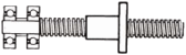
ALL TYPES FROM SIZE 10 TO SIZE 40 FROM STOCK.
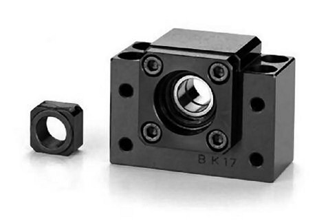
With paired precision a/c bearings
for drive end mounting
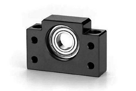
With single row radial bearing for
non drive end mounting
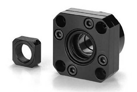
With paired precision a/c bearings
for drive end mounting
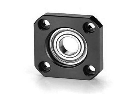
With single row radial bearing for
non drive end mounting
SCREW ENDS MACHINED TO SUIT THESE AND OTHER BEARING TYPES.
ALL TYPES OF MACHINED SCREW END FEATURES AVAILABLE.
Please enquire for dimensional and performance information.
| Order Cooling | Model No. | Surface Treatment | Applicable ballscrew accuracy grade | Bearing | 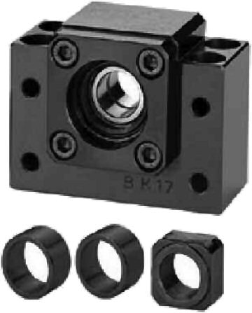 Black Oxide (Application : General case) |
|---|---|---|---|---|---|
| BK10_C7 | BK10 | Black Oxide | C7 | 7000A P0 | |
| BK10_C5 | C5 | ||||
| BK10_C3 | C3 | 7000A P5 | |||
| BK10_C7N | Electroless Nickel Plating | C7 | 7000A P0 | ||
| BK10_C5N | C5 | ||||
| BK10_C3N | C3 | 7000A P5 | |||
| BK12_C7 | BK12 | Black Oxide | C7 | 7001A P0 | |
| BK12_C5 | C5 | ||||
| BK12_C3 | C3 | 7001A P5 | |||
| BK12_C7N | Electroless Nickel Plating | C7 | 7001A P0 | ||
| BK12_C5N | C5 | ||||
| BK12_C3N | C3 | 7001A P5 | |||
| BK15_C7 | BK15 | Black Oxide | C7 | 7002A P0 | |
| BK15_C5 | C5 | ||||
| BK15_C3 | C3 | 7002A P5 | 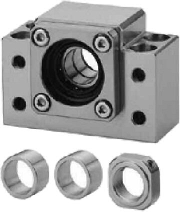 Electroless Nickel Plating (Application : Clean room) | ||
| BK15_C7N | Electroless Nickel Plating | C7 | 7002A P0 | ||
| BK15_C5N | C5 | ||||
| BK15_C3N | C3 | 7002A P5 | |||
| BK17_C7 | BK17 | Black Oxide | C7 | 7203A P0 | |
| BK17_C5 | C5 | ||||
| BK17_C3 | C3 | 7203A P5 | |||
| BK17_C7N | Electroless Nickel Plating | C7 | 7203A P0 | ||
| BK17_C5N | C5 | ||||
| BK17_C3N | C3 | 7203A P5 | |||
| BK20_C7 | BK20 | Black Oxide | C7 | 7004A P0 | |
| BK20_C5 | C5 | ||||
| BK20_C3 | C3 | 7004A P5 | |||
| BK20_C7N | Electroless Nickel Plating | C7 | 7004A P0 | ||
| BK20_C5N | C5 | ||||
| BK20_C3N | C3 | 7004A P5 |
NOTE
1. (Bearings are no Preload for C7 type support units, and Max. Axial clearance is 0.018mm)
2. (Bearings make Preload for C5 type support units, and Axial clearance is 0mm)
3. (All of bearings use Japan’s brand bearings)
| Order Cooling | Model No. | Surface Treatment | Applicable ballscrew accuracy grade | Bearing | Black Oxide (Application : General case) |
|---|---|---|---|---|---|
| BK25_C7 | BK25 | Black Oxide | C7 | 7205A P0 | |
| BK25B_C7 | C7 | 7205B P0 | |||
| BK25_C5 | C5 | 7205A P0 | |||
| BK25B_C5 | C5 | 7205B P0 | |||
| BK25_C3 | C3 | 7205A P5 | |||
| BK25_C7N | Electroless Nickel Plating | C7 | 7205A P0 | ||
| BK25B_C7N | C7 | 7205B P0 | |||
| BK25_C5N | C5 | 7205A P0 | |||
| BK25B_C5N | C5 | 7205B P0 | |||
| BK25_C3N | C3 | 7205A P5 | |||
| BK30_C7 | BK30 | Black Oxide | C7 | 7206A P0 | |
| BK30B_C7 | C7 | 7206B P0 | |||
| BK30_C5 | C5 | 7206A P0 | |||
| BK30B_C5 | C5 | 7206B P0 | |||
| BK30_C3 | C3 | 7206A P5 | |||
| BK30_C7N | Electroless Nickel Plating | C7 | 7206A P0 | Electroless Nickel Plating (Application : Clean room) | |
| BK30B_C7N | C7 | 7206B P0 | |||
| BK30_C5N | C5 | 7206A P0 | |||
| BK30B_C5N | C5 | 7206B P0 | |||
| BK30_C3N | C3 | 7206A P5 | |||
| BK35_C7 | BK35 | Black Oxide | C7 | 7207B P0 | |
| BK35_C5 | C5 | ||||
| BK35_C3 | C3 | 7207B P5 | |||
| BK35_C7N | Electroless Nickel Plating | C7 | 7207B P0 | ||
| BK35_C5N | C5 | ||||
| BK35_C3N | C3 | 7207B P5 | |||
| BK40_C7 | BK40 | Black Oxide | C7 | 7208B P0 | |
| BK40_C5 | C5 | ||||
| BK40_C3 | C3 | 7208B P5 | |||
| BK40_C7N | Electroless Nickel Plating | C7 | 7208B P0 | ||
| BK40_C5N | C5 | ||||
| BK40_C3N | C3 | 7208B P5 |
NOTE
1. (Bearings are no Preload for C7 type support units, and Max. Axial clearance is 0.018mm)
2. (Bearings make Preload for C5 type support units, and Axial clearance is 0mm)
3. (All of bearings use Japan’s brand bearings)
| Order Cooling | Model No. | Surface Treatment | Applicable ballscrew accuracy grade | Bearing | 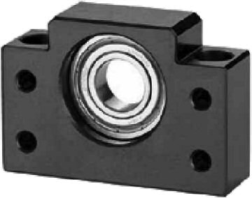 Black Oxide (Application : General case) |
|---|---|---|---|---|---|
| BF10_C7 | BF10 | Black Oxide | C7 | 608ZZ | |
| BF10_C3 | C3 C5 | 608ZZ | |||
| BF10_C7N | Electroless Nickel Plating | C7 | 608DD | ||
| BF10_C3N | C3 C5 | 608DD | |||
| BF12_C7 | BF12 | Black Oxide | C7 | 6000ZZ | |
| BF12_C3 | C3 C5 | 6000ZZ | |||
| BF12_C7N | Electroless Nickel Plating | C7 | 6000DDU | ||
| BF12_C3N | C3 C5 | 6000DDU | |||
| BF15_C7 | BF15 | Black Oxide | C7 | 6002ZZ | |
| BF15_C3 | C3 C5 | 6002ZZ | |||
| BF15_C7N | Electroless Nickel Plating | C7 | 6002DDU | ||
| BF15_C3N | C3 C5 | 6002DDU | |||
| BF17_C7 | BF17 | Black Oxide | C7 | 6203ZZ | |
| BF17_C3 | C3 C5 | 6203ZZ | |||
| BF17_C7N | Electroless Nickel Plating | C7 | 6203DDU | 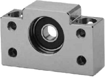 Electroless Nickel Plating (Application : Clean room) | |
| BF17_C3N | C3 C5 | 6203DDU | |||
| BF20_C7 | BF20 | Black Oxide | C7 | 6004ZZ | |
| BF20_C3 | C3 C5 | 6004ZZ | |||
| BF20_C7N | Electroless Nickel Plating | C7 | 6004DDU | ||
| BF20_C3N | C3 C5 | 6004DDU | |||
| BF25_C7 | BF25 | Black Oxide | C7 | 6205ZZ | |
| BF25_C3 | C3 C5 | 6205ZZ | |||
| BF25_C7N | Electroless Nickel Plating | C7 | 6205DDU | ||
| BF25_C3N | C3 C5 | 6205DDU | |||
| BF30_C7 | BF30 | Black Oxide | C7 | 6206ZZ | |
| BF30_C3 | C3 C5 | 6206ZZ | |||
| BF30_C7N | Electroless Nickel Plating | C7 | 6206DDU | ||
| BF30_C3N | C3 C5 | 6206DDU | |||
| BF35_C7 | BF35 | Black Oxide | C7 | 6207ZZ | NOTE
|
| BF35_C3 | C3 C5 | 6207ZZ | |||
| BF35_C7N | Electroless Nickel Plating | C7 | 6207DDU | ||
| BF35_C3N | C3 C5 | 6207DDU | |||
| BF40_C7 | BF40 | Black Oxide | C7 | 6208ZZ | |
| BF40_C3 | C3 C5 | 6208ZZ | |||
| BF40_C7N | Electroless Nickel Plating | C7 | 6208DDU | ||
| BF40_C3N | C3 C5 | 6208DDU |
| Order Cooling | Model No. | Surface Treatment | Applicable ballscrew accuracy grade | Bearing | 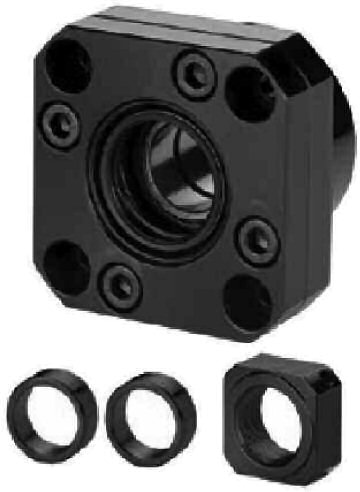 Black Oxide (Application : General case) |
|---|---|---|---|---|---|
| FK05_C7 | FK05 | Black Oxide | C7 | 605 | |
| FK05_C7N | Electroless Nickel Plating | C7 | 605 | ||
| FK06_C7 | FK06 | Black Oxide | C7 | 606 | |
| FK06_C5 | C5 | 706A P0 | |||
| FK06_C3 | C3 | 706A P5 | |||
| FK06_C7N | Electroless Nickel Plating | C7 | 606 | ||
| FK06_C5N | C5 | 706A P0 | |||
| FK06_C3N | C3 | 706A P5 | |||
| FK08_C7 | FK08 | Black Oxide | C7 | 608 | |
| FK08_C5 | C5 | 708A P0 | |||
| FK08_C3 | C3 | 708A P5 | |||
| FK08_C7N | Electroless Nickel Plating | C7 | 608 | ||
| FK08_C5N | C5 | 708A P0 | |||
| FK08_C3N | C3 | 708A P5 | |||
| FK10_C7 | FK10 | Black Oxide | C7 | 7000A P0 | 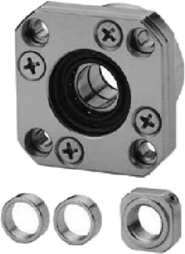 Electroless Nickel Plating (Application : Clean room) |
| FK10_C5 | C5 | ||||
| FK10_C3 | C3 | 7000A P5 | |||
| FK10_C7N | Electroless Nickel Plating | C7 | 7000A P0 | ||
| FK10_C5N | C5 | ||||
| FK10_C3N | C3 | 7000A P5 | |||
| FK12_C7 | FK12 | Black Oxide | C7 | 7001A P0 | |
| FK12_C5 | C5 | ||||
| FK12_C3 | C3 | 7001A P5 | |||
| FK12_C7N | Electroless Nickel Plating | C7 | 7001A P0 | ||
| FK12_C5N | C5 | ||||
| FK12_C3N | C3 | 7001A P5 | |||
| FK15_C7 | FK15 | Black Oxide | C7 | 7002A P0 | |
| FK15_C5 | C5 | ||||
| FK15_C3 | C3 | 7002A P5 | |||
| FK15_C7N | Electroless Nickel Plating | C7 | 7002A P0 | ||
| FK15_C5N | C5 | ||||
| FK15_C3N | C3 | 7002A P5 |
NOTE
1. (Bearings are no Preload for C7 type support units, and Max. Axial clearance is 0.018mm)
2. (Bearings make Preload for C5 type support units, and Axial clearance is 0mm)
3. (All of bearings use Japan’s brand bearings)
| Order Cooling | Model No. | Surface Treatment | Applicable ballscrew accuracy grade | Bearing | Black Oxide (Application : General case) |
|---|---|---|---|---|---|
| FK17_C7 | FK17 | Black Oxide | C7 | 7203A P0 | |
| FK17_C5 | C5 | 7203A P0 | |||
| FK17_C3 | C3 | 7203A P5 | |||
| FK17_C7N | Electroless Nickel Plating | C7 | 7203A P0 | ||
| FK17_C5N | C5 | 7203A P0 | |||
| FK17_C3N | C3 | 7203A P5 | |||
| FK20_C7 | FK20 | Black Oxide | C7 | 7204A P0 | |
| FK20B_C7 | C7 | 7204B P0 | |||
| FK20_C5 | C5 | 7204A P0 | |||
| FK20B_C5 | C5 | 7204B P0 | |||
| FK20_C3 | C3 | 7204A P5 | |||
| FK20_C7N | Electroless Nickel Plating | C7 | 7204A P0 | ||
| FK20B_C7N | C7 | 7204B P0 | |||
| FK20_C5N | C5 | 7204A P0 | Electroless Nickel Plating (Application : Clean room) | ||
| FK20B_C5N | C5 | 7204B P0 | |||
| FK20_C3N | C3 | 7204A P5 | |||
| FK25_C7 | FK25 | Black Oxide | C7 | 7205A P0 | |
| FK25B_C7 | C7 | 7205B P0 | |||
| FK25_C5 | C5 | 7205A P0 | |||
| FK25B_C5 | C5 | 7205B P0 | |||
| FK25_C3 | C3 | 7205A P5 | |||
| FK25_C7N | Electroless Nickel Plating | C7 | 7205A P0 | ||
| FK25B_C7N | C7 | 7205B P0 | |||
| FK25_C5N | C5 | 7205A P0 | |||
| FK25B_C5N | C5 | 7205B P0 | |||
| FK25_C3N | C3 | 7205A P5 | |||
| FK30_C7 | FK30 | Black Oxide | C7 | 7206A P0 | |
| FK30B_C7 | C7 | 7206B P0 | |||
| FK30_C5 | C5 | 7206A P0 | |||
| FK30B_C5 | C5 | 7206B P0 | |||
| FK30_C3 | C3 | 7206A P5 | NOTE
| ||
| FK30_C7N | Electroless Nickel Plating | C7 | 7206A P0 | ||
| FK30B_C7N | C7 | 7206B P0 | |||
| FK30_C5N | C5 | 7206A P0 | |||
| FK30B_C5N | C5 | 7206B P0 | |||
| FK30_C3N | C3 | 7206A P5 |
| Order Cooling | Model No. | Surface Treatment | Applicable ballscrew accuracy grade | Bearing | 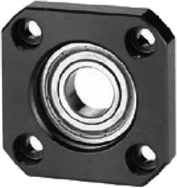 Black Oxide (Application : General case) |
|---|---|---|---|---|---|
| FF06_C7 | FF06 | Black Oxide | C7 | 606ZZ | |
| FF06_C3 | C3 C5 | 606ZZ | |||
| FF06_C7N | Electroless Nickel Plating | C7 | 606VV | ||
| FF06_C3N | C3 C5 | 606VV | |||
| FF10_C7 | FF10 | Black Oxide | C7 | 608ZZ | |
| FF10_C3 | C3 C5 | 608ZZ | |||
| FF10_C7N | Electroless Nickel Plating | C7 | 608DD | ||
| FF10_C3N | C3 C5 | 608DD | |||
| FF12_C7 | FF12 | Black Oxide | C7 | 6000ZZ | |
| FF12_C3 | C3 C5 | 6000ZZ | |||
| FF12_C7N | Electroless Nickel Plating | C7 | 6000DDU | ||
| FF12_C3N | C3 C5 | 6000DDU | |||
| FF15_C7 | FF15 | Black Oxide | C7 | 6002ZZ | |
| FF15_C3 | C3 C5 | 6002ZZ | |||
| FF15_C7N | Electroless Nickel Plating | C7 | 6002DDU | ||
| FF15_C3N | C3 C5 | 6002DDU | |||
| FF17_C7 | FF17 | Black Oxide | C7 | 6203ZZ | 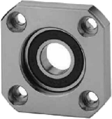 Electroless Nickel Plating (Application : Clean room) |
| FF17_C3 | C3 C5 | 6203ZZ | |||
| FF17_C7N | Electroless Nickel Plating | C7 | 6203DDU | ||
| FF17_C3N | C3 C5 | 6203DDU | |||
| FF20_C7 | FF20 | Black Oxide | C7 | 6204ZZ | |
| FF20_C3 | C3 C5 | 6204ZZ | |||
| FF20_C7N | Electroless Nickel Plating | C7 | 6204DDU | ||
| FF20_C3N | C3 C5 | 6204DDU | |||
| FF25_C7 | FF25 | Black Oxide | C7 | 6205ZZ | |
| FF25_C3 | C3 C5 | 6205ZZ | |||
| FF25_C7N | Electroless Nickel Plating | C7 | 6205DDU | ||
| FF25_C3N | C3 C5 | 6205DDU | |||
| FF30_C7 | FF30 | Black Oxide | C7 | 6206ZZ | |
| FF30_C3 | C3 C5 | 6206ZZ | |||
| FF30_C7N | Electroless Nickel Plating | C7 | 6206DDU | ||
| FF30_C3N | C3 C5 | 6206DDU |
NOTE
1. (Bearings are no Preload for C7 type support units, and Max. Axial clearance is 0.018mm)
2. (Bearings make Preload for C5 type support units, and Axial clearance is 0mm)
3. (All of bearings use Japan’s brand bearings)
| (mm) Fixed-side support unit ID (mm) | Fixed-side support unit applicable model | Supported-side support unit ID (mm) | Supported-side support unit applicable model | Applicable Ball Screw OD (mm) |
|---|---|---|---|---|
| 5 | EK05 | - | - | ∅6 |
| FK05 | ||||
| 6 | EK06 | 6 | EF06 | ∅8 |
| FK06 | FF06 | |||
| 8 | EK08 | 6 | EF08 | ∅10 |
| FK08 | FF06 | |||
| 10 | EK10 | 8 | EF10 | ∅10, ∅12, ∅14 |
| FK10 | FF10 | |||
| BK10 | BF10 | |||
| AK10 | AF10 | |||
| 12 | EK12 | 10 | EF12 | ∅14, ∅15, ∅16 |
| FK12 | FF12 | |||
| BK12 | BF12 | |||
| AK12 | AF12 | |||
| 15 | EK15 | 15 | EF15 | ∅20 |
| FK15 | FF15 | |||
| BK15 | BF15 | |||
| AK15 | AF15 | |||
| 17 | BK17 | 17 | BF17 | ∅20, ∅25 |
| FK17 | FF17 | |||
| 20 | EK20 | 20 | EF20 | ∅25, ∅28 |
| FK20 | FF20 | |||
| BK20 | BF20 | |||
| AK20 | AF20 | |||
| 25 | FK25 | 25 | FF25 | ∅32, ∅36 |
| BK25 | BF25 | |||
| 30 | FK30 | 30 | FF30 | ∅40, ∅45 |
| BK30 | BF30 | |||
| 35 | BK35 | 35 | BF35 | ∅45 |
| 40 | BK40 | 40 | BF40 | ∅50 |
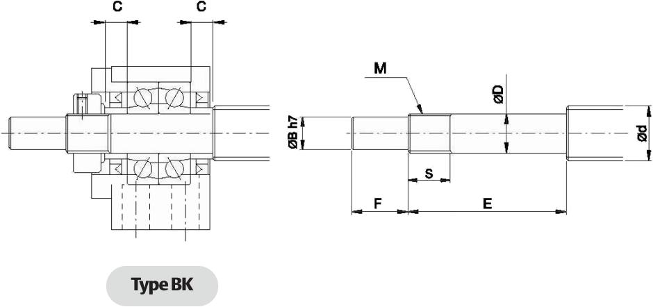
Units : mm
| Support unit model No. | Ballscrew shaft OD | Shaft support portion OD | Metric screw thread | Metric screw thread | |||||
|---|---|---|---|---|---|---|---|---|---|
| Type BK | d | D | B | E | F | M | S | C | |
| BK10 | 12/14/15 | 10 | -0.005 | 8 | 36 | 15 | M10x1 | 16 | 5.5 |
| -0.012 | |||||||||
| BK12 | 14/15/16 | 12 | -0.005 | 10 | 36 | 15 | M12x1 | 14 | 5.5 |
| -0.012 | |||||||||
| BK15 | 18/20 | 15 | -0.005 | 12 | 40 | 20 | M15x1 | 12 | 6 |
| -0.014 | |||||||||
| BK17 | 20/25 | 17 | -0.005 | 15 | 53 | 23 | M17x1 | 17 | 7 |
| -0.014 | |||||||||
| BK20 | 25/28 | 20 | -0.005 | 17 | 53 | 25 | M20x1 | 15 | 8 |
| -0.014 | |||||||||
| BK25 | 32/36 | 25 | -0.005 | 20 | 65 | 30 | M25x1.5 | 18 | 9 |
| -0.014 | |||||||||
| BK30 | 36/40 | 30 | -0.005 | 25 | 72 | 38 | M30x1.5 | 25 | 9 |
| -0.015 | |||||||||
| BK35 | 45 | 35 | -0.005 | 30 | 81 | 45 | M35x1.5 | 28 | 12 |
| -0.015 | |||||||||
| BK40 | 50 | 40 | -0.005 | 35 | 93 | 50 | M40x1.5 | 35 | 15 |
| -0.015 | |||||||||
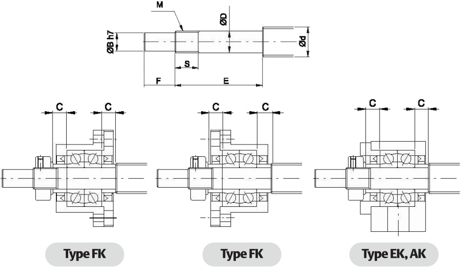
Units : mm
| Support unit model No. | Ballscrew shaft OD | Shaft support portion OD | Metric screw thread | Metric screw thread | |||||||
|---|---|---|---|---|---|---|---|---|---|---|---|
| Type FK | Type EK | Type AK | d | D | B | E | F | M | S | C | |
| FK05 | EK05 | - | 8 | 5 | -0.005 | 4 | 25 | 6 | M5x0.5 | 7 | 3.5 |
| -0.012 | |||||||||||
| FK06 | EK06 | - | 8 | 6 | -0.005 | 4 | 28 | 8 | M6x0.75 | 8 | 5 |
| -0.012 | |||||||||||
| FK08 | EK08 | - | 10/12 | 8 | -0.005 | 6 | 32 | 9 | M8x1 | 10 | 5.5 |
| -0.012 | |||||||||||
| FK10 | EK10 | AK10 | 12/14/15 | 10 | -0.005 | 8 | 36 | 15 | M10x1 | 11 | 5.5 |
| -0.012 | |||||||||||
| FK12 | EK12 | AK12 | 14/15/16 | 12 | -0.005 | 10 | 36 | 15 | M12x1 | 11 | 5.5 |
| -0.012 | |||||||||||
| FK15 | EK15 | AK15 | 18/20 | 15 | -0.005 | 12 | 47 | 20 | M15x1 | 13 | 10 |
| -0.014 | |||||||||||
| FK17 | - | - | 20/25 | 17 | -0.005 | 15 | 58 | 23 | M17x1 | 15 | 10 |
| -0.014 | |||||||||||
| FK20 | EK20 | AK20 | 25/28/30 | 20 | -0.005 | 17 | 62 | 25 | M20x1 | 17 | 11 |
| -0.014 | |||||||||||
| FK25 | - | - | 30/32/36 | 25 | -0.005 | 20 | 76 | 30 | M25x1.5 | 20 | 15 |
| -0.014 | |||||||||||
| FK30 | - | - | 36/40 | 30 | -0.005 | 25 | 72 | 38 | M30x1.5 | 25 | 9 |
| -0.015 | |||||||||||
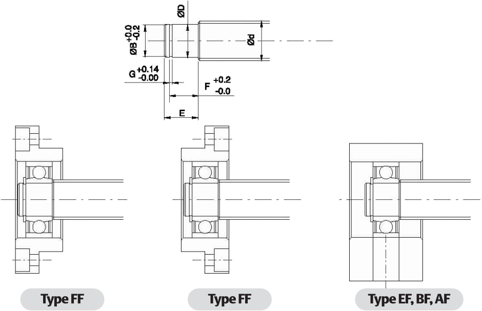
Units : mm
| Support unit model No. | Ballscrew shaft OD | Shaft support portion OD | ||||||||
|---|---|---|---|---|---|---|---|---|---|---|
| Type FF | Type EF | Type BF | Type AF | d | D | E | B | F | G | |
| FF06 | EF06 | - | - | 8 | 6 | -0.005 | 9 | 5.7 | 6.8 | 0.8 |
| -0.012 | ||||||||||
| - | EF08 | - | - | 10 | 6 | -0.005 | 9 | 5.7 | 6.8 | 0.8 |
| -0.012 | ||||||||||
| FF10 | EF10 | BF10 | AF10 | 12/14/15 | 8 | -0.005 | 10 | 7.6 | 7.9 | 0.9 |
| -0.012 | ||||||||||
| FF12 | EF12 | BF12 | AF12 | 14/15/16 | 10 | -0.005 | 11 | 9.6 | 9.15 | 1.15 |
| -0.012 | ||||||||||
| FF15 | EF15 | BF15 | AF15 | 18/20 | 15 | -0.005 | 13 | 14.3 | 10.15 | 1.15 |
| -0.014 | ||||||||||
| FF17 | - | BF17 | - | 20/25 | 17 | -0.005 | 16 | 16.2 | 13.15 | 1.15 |
| -0.014 | ||||||||||
| FF20 | EF20 | (BF20) Note | AF20 | 25/28/30 | 20 | -0.005 | 19 (16) | 19 | 15.35 (13.35) | 1.35 |
| -0.014 | ||||||||||
| FF25 | - | BF25 | - | 30/32/36 | 25 | -0.005 | 20 | 23.9 | 16.35 | 1.35 |
| -0.014 | ||||||||||
| FF30 | - | BF30 | - | 36/40 | 30 | -0.005 | 21 | 28.6 | 17.75 | 1.75 |
| -0.015 | ||||||||||
| - | - | BF35 | - | 40/45 | 35 | -0.005 | 22 | 33 | 18.75 | 1.75 |
| -0.015 | ||||||||||
| - | - | BF40 | - | 50 | 40 | -0.005 | 23 | 38 | 19.75 | 1.95 |
| -0.015 | ||||||||||
| SYK & THK | SYK & THK | KURODA | NSK | SYK & THK | KURODA | NSK | ||
|---|---|---|---|---|---|---|---|---|
| BK10 | EK05 | - | - | FK05 | - | - | ||
| BK12 | EK06 | BUK-6 | WBK06-01A | FK06 | - | WBK06-11 | ||
| BK15 | EK08 | BUK-8F | WBK08-01A | FK08 | BUM-8 | WBK08-11 | ||
| BK17 | EK10 | - | - | FK10 | BUM-10 | WBK10-11 | ||
| BK20 | EK12 | - | - | FK12 | BUM-12 | WBK12-11 | ||
| BK25 | EK15 | - | - | FK15 | BUM-15 | WBK15-11 | ||
| BK30 | EK20 | - | - | FK17 | - | - | ||
| BK35 | FK20 | BUM-20 | WBK20-11 | |||||
| BK40 | EF06 | - | - | FK25 | BUM-25 | WBK25-11 | ||
| EF08 | BUK-6S | WBK08S-01 | FK30 | - | - | |||
| BF10 | EF10 | - | - | |||||
| BF12 | EF12 | - | - | FF06 | - | - | ||
| BF15 | EF15 | - | - | FF10 | - | - | ||
| BF17 | EF20 | - | - | FF12 | - | - | ||
| BF20 | FF15 | - | - | |||||
| BF25 | SYK & THK | KURODA | NSK | FF17 | - | - | ||
| BF30 | AK10 | BUK-10F | WBK10-01A | FF20 | - | - | ||
| BF35 | AK12 | BUK-12F | WBK12-01A | FF25 | - | - | ||
| BF40 | AK15 | BUK-15F | WBK15-01A | FF30 | - | - | ||
| BK17 | - | WBK17-01A | ||||||
| AK20 | BUK-20F | WBK20-01A | ||||||
| - | BUK-25F | WBK25-01A | ||||||
| AF10 | BUK-8S | WBK10S-01 | ||||||
| AF12 | BUK-10S | WBK12S-01 | ||||||
| AF15 | BUK-15S | WBK15S-01 | ||||||
| BF17 | - | WBK17S-01 | ||||||
| AF20 | BUK-20S | WBK20S-01 | ||||||
| - | BUK-25S | WBK25S-01 | ||||||
| Model No. | Bearing | Static Load (Kgf) | Allowable Axial Load (Kgf) | Limiting RPM (RPM) | |
|---|---|---|---|---|---|
| FK06 | EK06 | 706 | 106 | 53 | |
| FK08 | EK08 | 708 | 148 | 74 | |
| BK10 | AK10 | 7000A | 266 | 133 | 16800 |
| FK10 | EK10 | ||||
| BK12 | AK12 | 7001A | 305 | 153 | 15400 |
| FK12 | EK12 | ||||
| BK15 | AK15 | 7002A | 350 | 175 | 13300 |
| FK15 | EK15 | ||||
| BK17 | FK17 | 7203A | 610 | 305 | 11200 |
| 7203B | 565 | 363 | 7700 | ||
| BK20 | 7004A | 670 | 335 | 10500 | |
| AK20 | 7204A | 845 | 423 | 9100 | |
| FK20 | EK20 | 7204B | 780 | 501 | 6650 |
| BK25 | FK25 | 7205A | 1050 | 525 | 8400 |
| 7205B | 960 | 617 | 5950 | ||
| BK30 | FK30 | 7206A | 1510 | 755 | 7000 |
| 7206B | 1380 | 887 | 4970 | ||
| BK35 | 7207B | 1870 | 1202 | 4200 | |
| BK40 | 7208B | 2340 | 1504 | 3710 | |
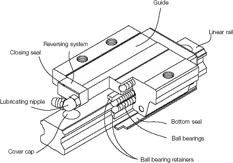
At Abssac, we concentrate on the flanged mount and square mount versions of linear guides. These items are in stock and have proven to be the best linear guide solution when teamed up with any of our ball and lead screw products. Dimensional data for these models can be accessed by the buttons above but we do encourage you to contact our knowledgeable sales team who can help you with the right selection..
By primarily using a four ball path design, within the slide, allows the guides to accept up to 30% more load and up to 30% stiffer than similar products in the market. An added bonus is that the ball bearings are retained within the housing so that should the guides come off the end of the rail, you will not be faced with all the ball bearings falling out. From experience, we know that this advantage can also significantly aid in the final assembly.
 Typical Guide applications include:
We also offer the advantage of supplying lightly pre-loaded heavy duty or extra heavy duty guide models to suit individual applications. When compared to other slide mechanisms such as dovetail slides, efficiency is far greater. The linear guides can carry loads in both horizontal and vertical directions. Please also note that the rails are pre drilled for ease of fitting and can be delivered cut to your desired length at no extra cost. Please note that all guides come with dust proofing seals at each end.
Available rail widths from 15mm to 65mm cater from the lightest to the heaviest load. If your application requires an accurate support and guide, our ex-stock range of linear rails may be the answer to your design challenges. Rails can be supplied from 100mm to 4000mm in length and in some cases can be attached to the application from beneath.
| HG Series 25, 30, 35 | Normal | High | Precision | Super Precision | Ultra Precision |
|---|---|---|---|---|---|
| Accuracy Class | +/- 0.1mm | +/- 0.04mm | +/- 0 | +/- 0 | +/- 0 |
| Height Tolerance H1 | +/- 0.1mm | +/- 0.04mm | + 0 /- 0.04mm | + 0 / 0.02mm | + 0 / 0.01mm |
| Width Tolerance N1 | +/- 0.1mm | +/- 0.04mm | + 0 /- 0.04mm | + 0 / 0.02mm | + 0 / 0.01mm |
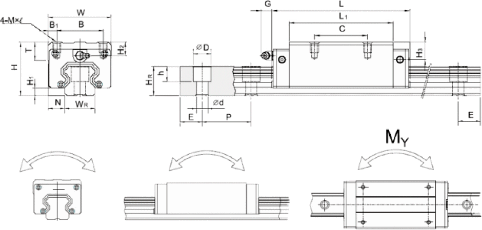
| Model No. | Dimensions of Assembly (mm) | Dimensions of Block (mm) | Dimensions of Rail (mm) | Mounting Bolt for Rail | Basic Dynamic Load Rating | Basic Static Load Rating | Static Rated Moment | Weight | |||||||||||||||||||||||
|---|---|---|---|---|---|---|---|---|---|---|---|---|---|---|---|---|---|---|---|---|---|---|---|---|---|---|---|---|---|---|---|
| H | H1 | N | W | B | B1 | C | L1 | L | K1 | K2 | G | MxL | T | H2 | H3 | WR | HR | D | h | d | P | E | (mm) | C (kN) | CO (kN) | MR kN-m | MP kN-m | MY kN-m | Block kg | Rail kg/m | |
| HGH 15CA | 24 | 4.3 | 9.5 | 34 | 26 | 4 | 26 | 39.4 | 61.4 | 10 | 4.85 | 5.3 | M4x5 | 6 | 7.95 | 7.7 | 15 | 15 | 7.5 | 5.3 | 4.5 | 60 | 20 | M4x16 | 11.38 | 16.97 | 0.12 | 0.10 | 0.10 | 0.18 | 1.45 |
| HGH 20CA | 30 | 4.6 | 12 | 44 | 32 | 6 | 36 | 50.5 | 77.5 | 12.25 | 6 | 12 | M5x6 | 8 | 6 | 7 | 20 | 17.5 | 9.5 | 8.5 | 6 | 60 | 20 | M5x16 | 17.75 | 27.76 | 0.27 | 0.20 | 0.20 | 0.30 | 2.21 |
| HGH 20HA | 50 | 65.2 | 92.2 | 12.6 | 21.18 | 35.90 | 0.35 | 0.35 | 0.35 | 0.39 | |||||||||||||||||||||
| HGH 25CA | 40 | 5.5 | 12.5 | 48 | 35 | 6.5 | 35 | 58 | 84 | 16.8 | 6 | 12 | M6x8 | 8 | 10 | 13 | 23 | 22 | 11 | 9 | 7 | 60 | 20 | M6x20 | 26.48 | 36.49 | 0.42 | 0.33 | 0.33 | 0.51 | 3.21 |
| HGH 25HA | 50 | 78.6 | 104.6 | 19.6 | 32.75 | 49.44 | 0.56 | 0.57 | 0.57 | 0.69 | |||||||||||||||||||||
| HGH 30CA | 45 | 6 | 16 | 60 | 40 | 10 | 40 | 70 | 97.4 | 20.25 | 6 | 12 | M8x10 | 8.5 | 9.5 | 13.8 | 28 | 26 | 14 | 12 | 9 | 80 | 20 | M8x25 | 38.74 | 52.19 | 0.66 | 0.53 | 0.53 | 0.88 | 4.47 |
| HGH 30HA | 60 | 93 | 120.4 | 21.75 | 47.27 | 69.16 | 0.88 | 0.92 | 0.92 | 1.16 | |||||||||||||||||||||
| HGH 35CA | 55 | 7.5 | 18 | 70 | 50 | 10 | 50 | 80 | 112.4 | 20.6 | 7 | 12 | M8x12 | 10.2 | 16 | 19.6 | 34 | 29 | 14 | 12 | 9 | 80 | 20 | M8x25 | 49.52 | 69.16 | 1.16 | 0.81 | 0.81 | 1.45 | 6.30 |
| HGH 35HA | 72 | 105.8 | 138.2 | 22.5 | 60.21 | 91.63 | 1.54 | 1.40 | 1.40 | 1.92 | |||||||||||||||||||||
| HGH 45CA | 70 | 9.5 | 20.5 | 86 | 60 | 13 | 60 | 97 | 139.4 | 23 | 10 | 12.9 | M10x17 | 16 | 18.5 | 30.5 | 45 | 38 | 20 | 17 | 14 | 105 | 22.5 | M12x35 | 77.57 | 102.71 | 1.98 | 1.55 | 1.55 | 2.73 | 10.41 |
| HGH 45HA | 80 | 128.8 | 171.2 | 28.9 | 94.54 | 136.46 | 2.63 | 2.68 | 2.68 | 3.61 | |||||||||||||||||||||
| HGH 55CA | 80 | 13 | 23.5 | 100 | 75 | 12.5 | 75 | 117.7 | 166.7 | 27.35 | 11 | 12.9 | M12x18 | 17.5 | 22 | 29 | 53 | 44 | 23 | 20 | 16 | 120 | 30 | M14x45 | 114.44 | 148.33 | 3.69 | 2.64 | 2.64 | 4.17 | 15.08 |
| HGH 55HA | 95 | 155.8 | 204.8 | 36.4 | 139.35 | 196.20 | 4.88 | 4.57 | 4.57 | 5.49 | |||||||||||||||||||||
| HGH 65CA | 90 | 15 | 31.5 | 126 | 76 | 25 | 70 | 144.2 | 200.2 | 43.1 | 14 | 12.9 | M16x20 | 25 | 15 | 15 | 63 | 53 | 26 | 22 | 18 | 150 | 35 | M16x50 | 163.63 | 215.33 | 6.65 | 4.27 | 4.27 | 7.00 | 21.18 |
| HGH 65HA | 120 | 203.6 | 259.6 | 47.8 | 208.36 | 303.13 | 9.38 | 7.38 | 7.38 | 9.82 | |||||||||||||||||||||
Note: 1kgf = 9.81N
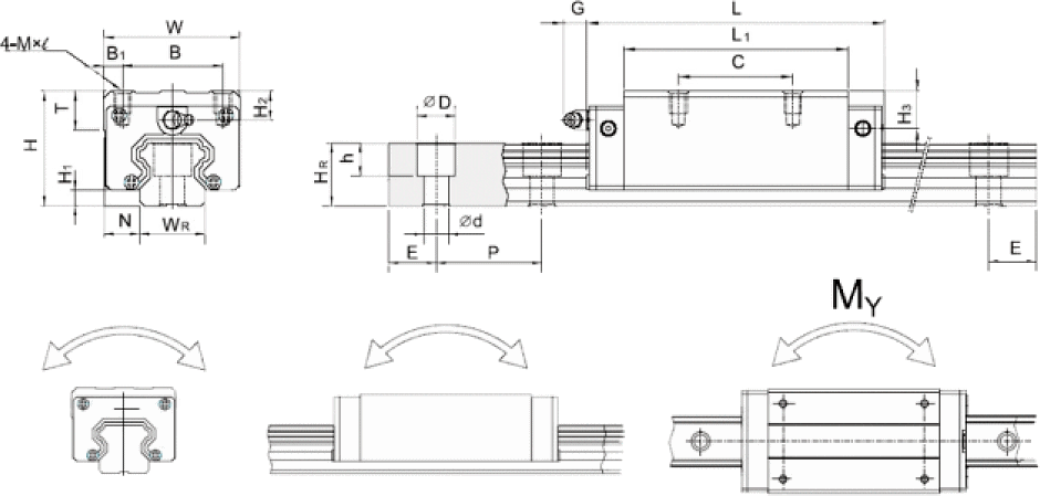
| Model No. | Dimensions of Assembly (mm) | Dimensions of Block (mm) | Dimensions of Rail (mm) | Mounting Bolt for Rail | Basic Dynamic Load Rating | Basic Static Load Rating | Static Rated Moment | Weight | |||||||||||||||||||||||
|---|---|---|---|---|---|---|---|---|---|---|---|---|---|---|---|---|---|---|---|---|---|---|---|---|---|---|---|---|---|---|---|
| H | H1 | N | W | B | B1 | C | L1 | L | K1 | K2 | G | MxL | T | H2 | H3 | WR | HR | D | h | d | P | E | (mm) | C (kN) | CO (kN) | MR kN-m | MP kN-m | MY kN-m | Block kg | Rail kg/m | |
| HGH 15CA | 24 | 4.3 | 16 | 47 | 38 | 4.5 | 30 | 39.4 | 61.4 | 8 | 4.85 | 5.3 | M5 | 6 | 7.95 | 7.7 | 15 | 15 | 7.5 | 5.3 | 4.5 | 60 | 20 | M4x16 | 11.38 | 16.97 | 0.12 | 0.10 | 0.10 | 0.17 | 1.45 |
| HGH 20CA | 30 | 4.6 | 21.5 | 63 | 53 | 5 | 40 | 50.5 | 77.5 | 10.25 | 6 | 12 | M6 | 8 | 6 | 7 | 20 | 17.5 | 9.5 | 8.5 | 6 | 60 | 20 | M5x16 | 17.75 | 27.76 | 0.27 | 0.20 | 0.20 | 0.40 | 2.21 |
| HGH 20HA | 65.2 | 92.2 | 17.6 | 21.18 | 35.90 | 0.35 | 0.35 | 0.35 | 0.52 | ||||||||||||||||||||||
| HGH 25CA | 36 | 5.5 | 23.5 | 70 | 57 | 6.5 | 45 | 58 | 84 | 11.8 | 6 | 12 | M8 | 8 | 6 | 9 | 23 | 22 | 11 | 9 | 7 | 60 | 20 | M6x20 | 26.48 | 36.49 | 0.42 | 0.33 | 0.33 | 0.59 | 3.21 |
| HGH 25HA | 78.6 | 104.6 | 22.1 | 32.75 | 49.44 | 0.56 | 0.57 | 0.57 | 0.80 | ||||||||||||||||||||||
| HGH 30CA | 42 | 6 | 31 | 90 | 72 | 9 | 52 | 70 | 97.4 | 14.25 | 6 | 12 | M10 | 8.5 | 6.5 | 10.8 | 28 | 26 | 14 | 12 | 9 | 80 | 20 | M8x25 | 38.74 | 52.19 | 0.66 | 0.53 | 0.53 | 1.09 | 4.47 |
| HGH 30HA | 93 | 120.4 | 25.75 | 47.27 | 69.16 | 0.88 | 0.92 | 0.92 | 1.44 | ||||||||||||||||||||||
| HGH 35CA | 48 | 7.5 | 33 | 100 | 82 | 9 | 62 | 80 | 112.4 | 14.6 | 7 | 12 | M10 | 10.1 | 9 | 12.6 | 34 | 29 | 14 | 12 | 9 | 80 | 20 | M8x25 | 49.52 | 69.16 | 1.16 | 0.81 | 0.81 | 1.56 | 6.3 |
| HGH 35HA | 105.8 | 138.2 | 27.5 | 60.21 | 91.63 | 1.54 | 1.40 | 1.40 | 2.06 | ||||||||||||||||||||||
| HGH 45CA | 60 | 9.5 | 37.5 | 120 | 100 | 10 | 80 | 97 | 139.4 | 13 | 10 | 12.9 | M12 | 15.1 | 8.5 | 20.5 | 45 | 38 | 20 | 17 | 14 | 105 | 22.5 | M12x35 | 77.57 | 102.71 | 1.98 | 1.55 | 1.55 | 2.79 | 10.41 |
| HGH 45HA | 128.8 | 171.2 | 28.9 | 94.54 | 136.46 | 2.63 | 2.68 | 2.68 | 3.69 | ||||||||||||||||||||||
| HGH 55CA | 70 | 13 | 43.5 | 140 | 116 | 12 | 95 | 117.7 | 166.7 | 17.35 | 11 | 12.9 | M14 | 17.5 | 12 | 19 | 53 | 44 | 23 | 20 | 16 | 120 | 30 | M14x45 | 114.44 | 148.33 | 3.69 | 2.64 | 2.64 | 4.52 | 15.08 |
| HGH 55HA | 155.8 | 204.8 | 36.4 | 139.35 | 196.20 | 4.88 | 4.57 | 4.57 | 5.96 | ||||||||||||||||||||||
| HGH 65CA | 90 | 15 | 53.5 | 170 | 142 | 14 | 110 | 144.2 | 200.2 | 23.1 | 14 | 12.9 | M16 | 25 | 15 | 15 | 63 | 53 | 26 | 22 | 18 | 150 | 35 | M16x50 | 163.63 | 215.33 | 6.65 | 4.27 | 4.27 | 9.17 | 21.18 |
| HGH 65HA | 203.6 | 259.6 | 52.8 | 208.36 | 303.13 | 9.38 | 7.38 | 7.38 | 12.89 | ||||||||||||||||||||||
Note: 1kgf = 9.81N
Storage temperature should be controlled to between 1 and 40°C.
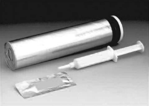
Designed for the effective lubrication and protection of all types of Abssac bronze nuts.
Temperature range -30°C to 150°C.
Revolutionary multi-complex soap technology.
Greatly extended lubrication intervals typically 3 times longer than conventional soap thickened greases.
Good corrosion resistance.
Blue in colour for high visibility.
Apply manually.
Compatible with other soap thickened greases.
However, for best results, the previous lubricant should be removed prior to application.
Please call us for a quotation.
 Overview
We offer a full complement of lubricants including our low vapour pressure greases for clean room and vacuum application. The TriGel line is specifically formulated to offer a lubrication solution for a wide range of linear motion applications. Choose the appropriate gel for your requirements and get the utmost performance out of your Danaher Motion products.
| TriGel-300S | TriGel-450R | TriGel-600SM | TriGel-1200SC | TriGel-1800RC | |
|---|---|---|---|---|---|
| Application | Lead Screws, Supernuts, Plastic Nuts | Ball Screws, Linear Bearings | Bronze Nuts | Lead Screws, Plastic Nuts, Clean Room, High Vacuum | Ball Screws, Linear Bearings, Bronze Nuts, Clean Room, Vacuum |
| Maximum Temperature | 200 °C (392 °F) | 125 °C (257 °F) | 125 °C (257 °F) | 250 °C (482 °F) | 125 °C (257 °F) |
| Mechanism | Plastic on Plastic or Metal | Metal on Metal | Metal on Metal Bronze on Steel | Plastic on Metal Combination | Metal on Metal |
| Mechanical Load | Light | Moderate | Moderate to Heavy | Light to Moderate | Moderate |
| Very Low Torque Variation over Temperature | Yes | - | - | Yes | - |
| Very Low Starting Torque | Yes | Yes | - | Yes | Yes |
| Compatibility with Reactive Chemicals | Not recommended w/o OEM testing | Not recommended w/o OEM testing | Not recommended w/o OEM testing | Usually OK | Not recommended w/o OEM testing |
| Compatibility with Plastics and Elastomers | May cause silicon rubber seals to swell | May cause EPDM seals to swell | May cause EPDM seals to swell | Usually OK | May cause EPDM seals to swell |
| Clean Room Use | Not recommended | Not recommended | Not recommended | Usually OK | Usually OK |
| High Vacuum U se | Not recommended | Not recommended | Not recommended | Usually OK | Usually OK |
| Vapor Pressure (25°C) | Varies with lot | Varies with lot | Varies with lot | 1 × 10⁻⁶ Pa | 0,5 × 10⁻⁶ Pa |
| Packaging 10-cc-Syringe 0,45-kg-Tube | TriGel-300S TriGel-300S-1 | 7832867/TriGel-450R 7832868/TriGel-450R-1 | 0,1-kg-Tube/TriGel-600SM | TriGel-1200SC n.z. | 7832869/TriGel-1800RC |
* Maximum temperature for continuous exposure. Higher surge temperatures may be
permissible but should be validated in the actual end use by the OEM.
Low temperature limits are -15°C or lower. Consult Danaher Motion for specifics.
 PTFE coating is a dry film which creates a lubrication barrier between a metal substrate and a polymer bushing or lead nut. It can in some cases eliminate the need for an additional gel type lubricant which must be reapplied. It is well suited for use with our SuperNut line of plastic nuts and stainless steel lead screws. Lubrication maintenance intervals can be eliminated and the coating does not attract particulate like a gel lubricant. Gel lubricants can provide lower friction coefficients than dry film lubricants but must be maintained to prevent performance degradation. PTFE coating provides an attractive and clean* alternative to gels and oils.
| Type: | Bonded Solid Film Lubricant |
|---|---|
| Purpose: | Increased Lubricity, Decreased Friction & Wear |
| Appearance: | Black Coating |
| Thickness: | Approx. 13 – 25 micron |
| Active Lubricant: | Polytetrafluroethylene |
| Friction Coefficient: | 0,06 to 0,12 |
| Temperature Operating Range: | -250° to 290° C |
| Resistance to Acids: | Excellent |
| Resistance to Bases: | Very Good |
| Resistance to Solvents: | Excellent |
* Some particulate will be generated as a result of wear between nut and screw.
Screw may begin to show signs of “polishing” over time. This does not necessarily indicate failure.
Name | Company | ||||
Address | |||||
Tel | Fax | E-Mail | |||
| OPERATING LOADS | |||||
Normal operating loadKilo/lbs | |||||
Load is in tension | Load is in compression | Load is in both | |||
Load is constant | Load is variable | ||||
| (If load is variable submit load curve diagram.) | |||||
Maximum static load in tensionKilo/lbs | |||||
Maximum static load in compressionKilo/lbs | |||||
Sideloads if any | Overturning moment (cantilever loads) | ||||
Describe | |||||
| DUTY CYCLE | |||||
Continuous operation | Intermittent operation | Variable | |||
Time under dynamic load | Time at rest | ||||
Describe operation | |||||
| METHOD OF OPERATION | |||||
Screw will be driven | Nut will be driven | ||||
The force will be applied to the nut to rotate the screw (back driven screw) | |||||
Assembly will be lubricated | Type of lube | ||||
| Please ask our technical staff for recommendations for the best lubricant for your application. | |||||
| SPEED AND TRAVEL RATE | |||||
Rate of travel described in inches per minute | |||||
Input RPM at screw or nut | |||||
Amount of torque available | |||||
| TRAVEL LENGTH AND SUPPORTS | ||
What is the unsupported screw length between bearingsin/mm | ||
Does the nut travel the full length of the screwin/mm | ||
If not, over what area does the nut travel | ||
Is the screw operated in a vertical | Horizontal | Other, please state |
What type of end supports are you using? | ||
| LEAD ACCURACY | ||
Standard accuracy (.015 in per ft max) / 0.3mm per 300mm) | ||
Precision rolled thread accuracy required (0.003 in per ft) / (.07mm per 300mm) | ||
Ground precision accuracy required (.0005 in per ft) / (.01mm per 300mm) | ||
Better than the above required? Please state 0.0mm / 300mm | ||
| SCREW SIZE | ||
Standard backlash OK (up to .007in) / (.1778mm) | ||
Reduced backlash required (.002 in max) / (.0508mm) | ||
Zero backlash required | ||
| ENVIRONMENT | ||
Will operate at normal room temperature | Will operate in very dirty / dusty conditions | |
Will operate at very high temperatures | Will operate where metal chips are present | |
Will operate at very low temperatures | Will operate in corrosive atmosphere | |
| STRAIGHTNESS | ||
Standard straightness OK (.01in per ft) 0.254mm / 300mm | ||
Special straightness required (.002in per ft) 0.0508mm / 300mm | ||
Straightness better than 0.002in per ft required 0.0508mm / 300mm | ||
| END MACHINING | ||
| If you want to order the screws with the ends already machined to your specifications, submit a sketch or drawing with details and tolerances required. | ||
| QUOTATION INFORMATION | ||
Quantity desired | ||
Delivery schedule | ||
| Please submit any additional data you feel would be helpful to us in selecting the proper screw size and in submitting your quotation. Attach drawings of screw and nut if available. Suggestions, help and advice is given in good faith but without responsibility. It remains the responsibility of the customer or end user to ensure that the product chosen meets their life, duty cycle and other performance criteria. | ||
"ABSSAC" is a registered trade mark 2375859
All rights are reserved.
The use of this catalogue is made available to you by Abssac Limited. The exclusive right to control the use of the copyright and trademarks on this site is controlled by Abssac Limited. These may not be copied, reproduced, published, distributed, modified or otherwise used in any form including electronic copying without the express permission of Abssac Limited. Abssac Limited has made all reasonable endeavor to ensure that the material on this site is accurate. You agree that Abssac Limited, nor any other person involved in creating or providing this catalogue shall be liable for any indirect or consequential damage arising from the use of any information contained in this catalogue.
The information contained in this catalogue is provided 'as is' without warranty of any kind, either expressed or implied. Abssac Limited assumes no responsibility for errors or omissions in this catalogue or other documents which are reference by or linked to this catalogue. This catalogue could include technical or other inaccuracies including typographical errors. Updates and changes are periodically added to the information herein; these changes will be incorporated in new editions of this catalogue. Abssac Limited may make improvements and/or changes in the product(s) or service(s) described in this publication at any time. You agree that the above terms represent the entire basis of the agreement between us, upon which you are permitted to enter this site and you agree that all relations between us are subject to the Law of England and Wales.