![]()
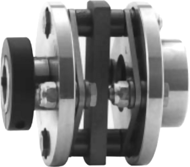
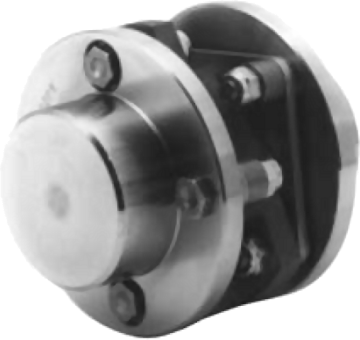
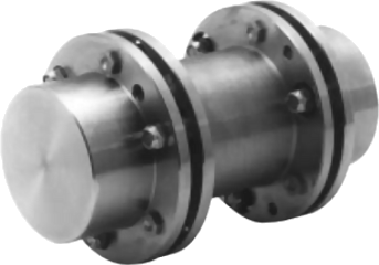
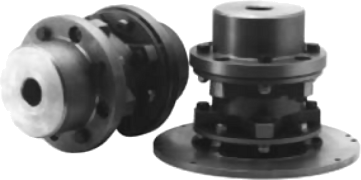
Form-Flex couplings transmit torque while compensating for angular, parallel and axial misalignment between two connected shafts. Flexible disc couplings minimize the misalignment forces on the connected equipment.
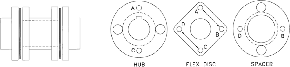
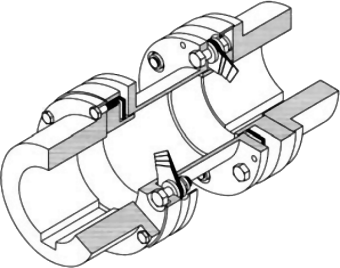
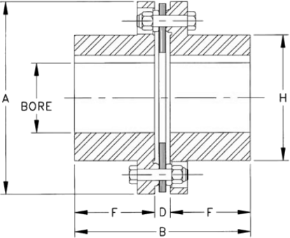
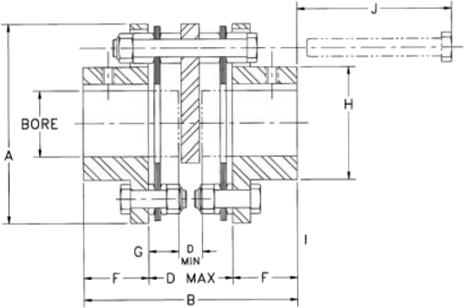
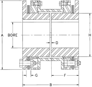
The Basic Flex coupling consists of two hubs, a spacer and two flexible discs. The flex disc is an assembly of thin metal laminations. In figure shown below, flex disc holes A & C are bolted to the hub and holes B & D are bolted to the spacer. Torque is transmitted in direct tensions from A to B and from C to D through the flex disc. Misalignment is taken through bending in the link between the bolt holes.
Form-Flex metal disc couplings are widely used in cooling fan drive applications. Form-Flex 4 bolt disc couplings offer more misalignment capacity than any competing metal disc design.
For smaller towers up to about 100 inches DBSE, we offer steel and composite spacer tubing options. TrueTube composite torque tubes are lighter than steel and eliminate thermal growth and vibration problems.
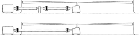
Form-Flex composite floating shaft couplings are recommended as a replacement for older multi-section drivelines. Composite couplings can span up to 240 inches without high maintenance centre support bearings.
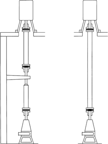
Form-Flex floating shaft couplings are a costeffective, maintenace free alternative to cardan U-joints for vertical pump drivelines. Form-flex couplings are available with either steel or composite spacer tubing. Composite spacer tubing can reduce total cost by eliminating the need for bearings and support structures.
| DISC STYLE | DESIGN FEATURES | WHERE USED |
|---|---|---|
4 bolt (A, M Series) | Straight sided flex disc. 1 degree angular misalignment. Torque range: 35 lb.in. to 30,240 lb. in. Zero backlash. All machined steel construction. Stainless steel flex discs. Steel or stainless steel materials. Minimum reaction forces. | Ideal for general industrial applications with motor or turbine drivers and smooth to moderate load conditions. Low to moderate speed ranges. Serve or stepper driven positioning systems. Applications where misalignment may be a problem. 4 bold designs offer the highest misalignment capacity of any metal disc design. Not recommended for engine driven applications. |
6 bolt (B Series) | Straight sided disc. 0.7 degree angular misalignment. Torque range: 3050 lb.in. to 233,000 lb.in. Suitable for precision balancing. Zero backlash. All machined steel construction. Stainless steel flex discs. Steel or stainless steel materials. | Ideal for motor or turbine drivers with any load conditions. Use for reversing, reciprocating or other rough load conditions. May be used with industrial engines driving smooth loads. Moderate to high speed ranges and applications where dynamic balancing is required. Consider 6 bolt where 4 bolt size requires increasing coupling size to meet bore size requirements. |
8 bolt (D, F, H Series) | Round disc design. 0.3 degree angular misalignment. Torque range: 9500 lb.in. to 2,000,000 lb.in. Zero backlash. Heavy duty cast construction. Alloy or stainless steel flex discs. Flywheel mount designs. | High torque-low speed applications. Industrial engines driving reciprocating equipment. Heavy-duty reversing applications. Custom designs for high torque applications. |
| MATERIAL CLASSES - Applies to 4 and 6 Bolt Designs | ||||
|---|---|---|---|---|
| MATERIAL CLASS BY COMPONENT | DESCRIPTION | |||
| COUPLING | HUB | SPACER ASSY | REPAIR KIT | |
| A | A | A | A | Mild steel hubs and spacer, alloy steel hardware, 300 series SS flex disc |
| B | B | B | A | Zinc plated steel hubs and spacer, alloy steel hardware, 300 series SS flex disc |
| C | B | C | E | Zinc plated steel hubs and spacer, 300 series SS flex disc and hardware |
| E | E | E | E | All 300 series stainless steel construction |
| PRODUCT FEATURES AND OPTIONS | ||||||||
|---|---|---|---|---|---|---|---|---|
| FEATURE | AR, AK, AP AX, AY | BH, BP, BY, DP* | BF | BA, DA* | A5, A7 | B5 | HFTH | HH, HSH, FSH |
| STANDARD BORE FIT | Clearance | Interference | Clearance | Interference | ||||
| SET SCREWS | Standard | Optional | Standard | Optional | ||||
| PULLER HOLES | Optional | Standard | Optional | Standard | Optional | |||
| STANDARD FLEX DISCS | 300 Series Stainless Steel* | Alloy Steel | ||||||
| BALANCE CLASS | AGMA 7 | AGMA 8 | AGMA 9 | AGMA 7 | N/A | N/A | ||
| DYNAMIC BALANCE | Optional | Per TBW Commercial Standard | N/A | |||||
* Alloy steel flex disc is standared for DA and DP series. Stainless steel is optional.
| COUPLING TYPE | TYPICAL APPLICATIONS | SERIES | |
|---|---|---|---|
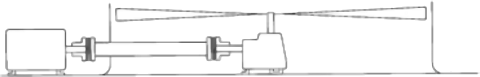
| SINGLE FLEX | Single flexing couplings compensate for angular and axial misalignment only. Single couplings should only be used in a three bearing system with a self-aligning bearing as shown in the illustration. Single couplings may also be used in pairs to support a clutch, transducer or other system component. These arrangements are double flexing and must be used with two fully supported shafts as described below. | 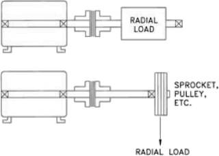 | AR BH HH |
| CLOSE COUPLE DOUBLE FLEX | Close couple designs accommodate angular, parallel and axial misalignment types where two fully supported shafts are located very close together. Close shaft separations are generally in the range of 1/8 to 2 inches. | 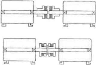 | AX AA AY BY BA DA |
| SPACER COUPLINGS DOUBLE FLEX | Spacer couplings are used to connect fully supported shafts with wider separations than can be reached with a close couple design. Spacer couplings allow room for installation and maintenance without moving the connected equipment. Shaft separations are generally in the range of 3 to 12 inches. These couplings accommodate angular, parallel and axial misalignment. | 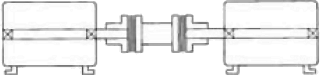 | AK AP BP BF DP HSH FSH |
| FLOATING SHAFT COUPLINGS | Floating shaft couplings are spacer style couplings which are designed to connect widely separated shafts.The coupling spacers are fabricated. Both steel and TrueTube composite tubing options are available. Semi-floating shaft couplings are a special single flex version of the floating shaft coupling. These may be used alone for some applications or in combination with floating shaft couplings and pillow block bearings to span long distances. Composite floating shaft couplings should be considered as an alternative to mutiple span applications with centre bearings. | 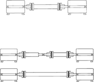 | A5 A7 B5 HFTH C/S |
| MICRO COUPLINGS DOUBLE FLEX | Form-Flex Micro Couplings are used for precision low torque applications.They are a smaller version of our 4 bolt line. Micro Couplings are constructed of aluminum for reduced inertia. Close couple and spacer designs are available. | 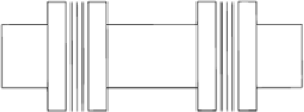 | MA MB MC |
| SERVICE FACTOR TABLE | |||||||
|---|---|---|---|---|---|---|---|
| These service factors assume a smooth motor or turbine type driver. The adders listed for other driver types must be added to the service factor shown for the driven equipment. | |||||||
| ADDERS FOR DRIVER TYPE | DRIVEN EQUIPMENT | S.F. | DRIVEN EQUIPMENT | S.F. | DRIVEN EQUIPMENT | S.F. | |
| DRIVER | ADD | CONVEYORS - Uniform Load (cont.) | FANS | PAPER MILLS - (cont.) | |||
| TURBINE | 0 | Flight | 1.25 | Centrifugal | 1.00 | Couch | 1.75 |
| AC MOTORS | Oven | 1.50 | Cooling Tower | 2.00 | Cutters, Platers | 2.00 | |
| With Soft Start | 0 | Screw | 1.25 | FEEDERS | Cylinders | 1.75 | |
| NEMA A or B | 0 | CONVEYORS - Non-uniform Load | Aprons | 1.25 | Dryers | 1.75 | |
| NEMA C or D | 1 | Apron | 1.50 | Belt | 1.25 | Felt Stretchers | 1.25 |
| DC MOTORS | Assembly | 1.25 | Disc | 1.25 | Felt Whipper | 2.00 | |
| Shunt Type | 0 | Belt | 1.25 | Reciprocating | 2.50 | Presses | 2.00 |
| Series or Compund | 1 | Bucket | 1.50 | Screw | 1.25 | Reel | 1.50 |
| I/C ENGINES | Chain | 1.50 | FOOD INDUSTRY | Stock Chests | 1.50 | ||
| 8 or more Cylinders | 1 | Flight | 1.50 | Cereal Cookers | 1.25 | Suction Roll | 1.75 |
| 4-6 Cylinders | 1.5 | Oven | 1.50 | Dough Mixers | 1.75 | Washers and Thickeners | 1.50 |
| 1-3 Cylinders | 2 | Reciprocating | 2.50 | Meat Grinders | 1.75 | Winders | 1.50 |
| DRIVEN EQUIPMENT | S.F. | Screw | 1.50 | Slicers | 1.75 | PRINTING PRESSES | 1.50 |
| Shaker | 2.50 | LUMBER INDUSTRY | PUMPS | ||||
| AGITATORS | CRANES AND HOISTS | Barkers-Drum Type | 2.00 | Centrifugal | 1.00 | ||
| Pure Liquids | 1.00 | Main Cranes | 2.00 | Edger Feeders | 2.00 | Reciprocating Double Acting | 2.00 |
| Liquids and Solids | 1.25 | Reversing | 2.00 | Live Rolls | 2.00 | ||
| Liquids - Variable Density | 1.25 | Skip Hoists | 1.75 | Log Haul | 2.00 | Single Acting 1-2 Cylinders | 2.25 |
| BLOWERS | Trolley Drive | 1.75 | Off Bearing Rolls | 2.00 | Single Acting 3+ Cylinders | 1.75 | |
| Centrifugal | 1.00 | Bridge Drive | 1.75 | Planers | 1.75 | Rotary-Gear, Lobe, Vane | 1.50 |
| Lobe | 1.50 | Slope | 1.50 | Slab Conveyors | 1.50 | TEXTILE INDUSTRY | |
| Vane | 1.25 | DREDGES | Sorting Table | 1.50 | Batchers | 1.25 | |
| BRIQUETTER MACHINE | 1.00 | Cable Reels | 1.75 | Trimmer Feed | 1.75 | Calendars | 1.75 |
| CAN FILLING MACHINE | 1.00 | Conveyors | 1.50 | MACHINE TOOLS | Card Machines | 1.50 | |
| COMPRESSORS | Maneuvering Winches | 1.75 | Bending Roll | 2.00 | Cloth Finishing Machines | 1.50 | |
| Centrifugal | 1.25 | Pumps | 1.75 | Plate Planer | 1.50 | Dry Cans | 1.75 |
| Lobe | 1.50 | Screen Drives | 1.75 | Spindle Drives | 1.50 | Dryers | 1.50 |
| Reciprocating | C/F | Stracers | 1.75 | Table/Axis Drives | 1.25 | Dyeing Machinery | 1.25 |
| CONVEYORS - Uniform Load | Utility Winches | 1.50 | Tapping Machines | 2.50 | Looms | 1.50 | |
| Apron | 1.25 | ELEVATORS | PAPER MILLS | Mangles | 1.25 | ||
| Assembly | 1.00 | Bucket | 1.75 | Beater and Pulper | 1.75 | Nappers | 1.25 |
| Belt | 1.00 | Centrifugal Discharge | 1.50 | Bleacher | 1.00 | Soapers | 1.25 |
| Bucket | 1.25 | Freight | 2.00 | Calendars | 2.00 | Spinners | 1.50 |
| Chain | 1.25 | Gravity Discharge | 1.50 | Converting Machines | 1.50 | TINTER FRAMES | 1.50 |
| TYPICAL APPLICATION CONDITIONS | ||||||
|---|---|---|---|---|---|---|
| Smooth motor or turbine driven | Steady motor or turbine driven | Moderate motor or turbine driven | Medium motor or turbine driven | Heavy-high TQ, motor or engine driven | Extra heavy engine driven | Extremely heavy engine driven |
 |  |  |  |  |  |  |
| Soft start with steady load | Average starting loads and slight torque variations | Above average starting loads and moderate load variations | High starting• torques and medium to heavy load variations | Mild shock loading engines. Driving smooth loads. Extreme reliability | Heavy shock loading or light reversing | Extreme shock loading. Frequent wide torque variations |
| Type/Size | RATED TORQUE LB*IN | MAX RPM | O.D. | MAX BORE | SERVICE FACTOR | |||||||
|---|---|---|---|---|---|---|---|---|---|---|---|---|
| 1.0 | 1.5 | 2.0 | 2.5 | 3.0 | 3.25 | 4.0 | ||||||
| RATED HP/100RPM AT SERVICE FACTOR SHOWN | ||||||||||||
| Micro 4 bolt | 01 | 9 | 20,000 | 1.02 | 0.38 | 0.01 | 0.01 | 0.01 | NOT RECOMMENDED FOR THESE APPLICATIONS | |||
| 02 | 17 | 20,000 | 1.26 | 0.59 | 0.03 | 0.02 | 0.01 | |||||
| 03 | 35 | 20,000 | 1.65 | 0.79 | 0.06 | 0.04 | 0.03 | |||||
| 04 | 87 | 20,000 | 2.24 | 0.79 | 0.14 | 0.09 | 0.07 | |||||
| A Series 4 bolt | 05 | 300 | 8,500 | 2.65 | 0.87 | 0.48 | 0.32 | 0.24 | 0.19 | |||
| 10 | 800 | 7,500 | 3.19 | 1.25 | 1.27 | 0.85 | 0.63 | 0.51 | ||||
| 15 | 1.575 | 6,700 | 3.65 | 1.37 | 2.50 | 1.67 | 1.25 | 1.00 | ||||
| 20 | 2,200 | 6,200 | 4.08 | 1.62 | 3.49 | 2.33 | 1.75 | 1.40 | ||||
| 25 | 3,800 | 5,500 | 4.95 | 2.00 | 6.03 | 4.02 | 3.02 | 2.41 | ||||
| 30 | 6,930 | 5,000 | 5.63 | 2.37 | 11.00 | 7.33 | 5.50 | 4.40 | ||||
| 35 | 11,340 | 4,400 | 6.63 | 2.87 | 18.00 | 12.00 | 9.00 | 7.20 | ||||
| 40 | 18,270 | 4,000 | 7.64 | 3.25 | 29.00 | 19.33 | 14.50 | 11.60 | ||||
| 45 | 30,240 | 3,700 | 8.43 | 3.25 | 48.00 | 32.00 | 24.00 | 19.20 | ||||
| B Series 6 bolt | 33 | 3,050 | 17,400 | 4.69 | 2.50 | 4.84 | 3.23 | 2.42 | 1.94 | 1.61 | 1.49 | |
| 38 | 6,860 | 14,300 | 5.87 | 3.25 | 10.89 | 7.26 | 5.44 | 4.36 | 3.63 | 3.35 | ||
| 43 | 13,500 | 12,700 | 6.70 | 3.75 | 21.43 | 14.29 | 10.71 | 8.57 | 7.14 | 6.59 | ||
| 48 | 18,400 | 11,000 | 7.50 | 4.38 | 29.21 | 19.47 | 14.60 | 11.68 | 9.74 | 8.99 | ||
| 53 | 24,000 | 10,700 | 7.87 | 4.50 | 38.10 | 25.40 | 19.05 | 15.24 | 12.70 | 11.72 | ||
| 58 | 41,000 | 9,475 | 9.00 | 5.13 | 65.08 | 43.39 | 32.54 | 26.03 | 21.69 | 20.02 | ||
| 63 | 48,000 | 8,590 | 10.00 | 5.50 | 76.19 | 50.79 | 38.10 | 30.48 | 25.40 | 23.44 | ||
| 68 | 72,000 | 7,800 | 10.75 | 6.00 | 114.29 | 76.19 | 57.14 | 45.71 | 38.10 | 35.16 | ||
| 73 | 125,000 | 6,740 | 12.50 | 6.50 | 198.41 | 132.28 | 99.21 | 79.37 | 66.14 | 61.05 | ||
| 78 | 233,000 | 5,600 | 15.05 | 7.50 | 369.84 | 246.56 | 184.92 | 147.94 | 123.28 | 113.8 | ||
| D Series 8 bolt | 22 | 9,500 | 3,800 | 6.00 | 2.25 | 15.08 | 10.05 | 7.54 | 6.03 | 5.03 | 4.64 | 3.77 |
| 26 | 16,000 | 3,300 | 6.88 | 2.63 | 25.40 | 16.93 | 12.70 | 10.16 | 8.47 | 7.81 | 6.35 | |
| 31 | 24,000 | 2,800 | 8.13 | 3.13 | 38.10 | 25.40 | 19.05 | 15.24 | 12.70 | 11.72 | 9.52 | |
| 35 | 44,000 | 2,600 | 9.13 | 3.63 | 69.84 | 46.56 | 34.92 | 27.94 | 23.28 | 21.49 | 17.46 | |
| 37 | 60,000 | 2,500 | 10.06 | 3.75 | 95.24 | 63.49 | 47.62 | 38.10 | 31.75 | 29.30 | 23.81 | |
| 42 | 73,000 | 2,400 | 11.00 | 4.50 | 115.87 | 77.25 | 57.94 | 46.35 | 38.62 | 35.65 | 28.97 | |
| 45 | 99,000 | 2,250 | 11.88 | 4.75 | 157.14 | 104.76 | 78.57 | 62.86 | 52.38 | 48.35 | 39.29 | |
| 50 | 128,000 | 2,000 | 13.44 | 5.50 | 203.17 | 135.45 | 101.59 | 81.27 | 67.72 | 62.52 | 50.79 | |
| 55 | 189,000 | 1,800 | 15.00 | 6.25 | 300.00 | 200.00 | 150.00 | 120.00 | 100.00 | 92.31 | 75.00 | |
| 60 | 261,000 | 1,600 | 16.75 | 7.12 | 414.29 | 276.19 | 207.14 | 165.71 | 138.10 | 127.47 | 103.57 | |
| 70 | 415,000 | 1,400 | 18.94 | 7.87 | 658.73 | 439.15 | 329.37 | 263.49 | 219.58 | 202.69 | 164.68 | |
| 75 | 533,000 | 1,300 | 20.63 | 8.75 | 846.03 | 564.02 | 423.02 | 338.41 | 282.01 | 260.32 | 211.51 | |
| 80 | 685,000 | 1,200 | 22.38 | 9.12 | 1,087.30 | 724.87 | 543.65 | 434.92 | 362.43 | 334.55 | 271.83 | |
| 85 | 829,000 | 1,100 | 23.75 | 9.62 | 1,315.87 | 877.25 | 657.94 | 526.35 | 438.62 | 404.88 | 328.97 | |
| 92 | 1,040,000 | 1,000 | 25.75 | 11.00 | 1,650.79 | 1,100.53 | 825.40 | 660.32 | 550.26 | 507.94 | 412.70 | |
| 105 | 1,250,000 | 1,000 | 29.25 | 12.00 | 1,984.13 | 1,322.75 | 992.06 | 793.65 | 661.38 | 610.50 | 496.03 | |
| 160 | 2,000,000 | 900 | 33.50 | 17.00 | 3,174.60 | 2,116.40 | 1,587.30 | 1,269.84 | 1,058.20 | 976.80 | 793.65 | |
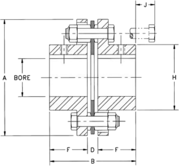
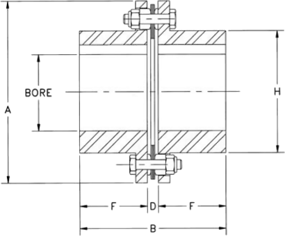
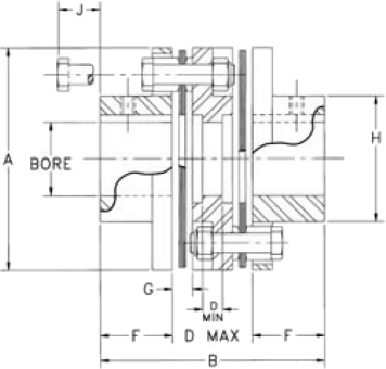
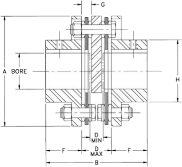
To order a complete coupling, order two hubs of any time and a coupling (spacer) sub assembly for the required coupling type. All dimensions shown in inches. | |||||||||||||||
AJ Standard HubsProvided with straight bore and keyway solid hubs available from stock | AZ Oversize Bore HubsProvided with straight bore and keyway | ||||||||||||||
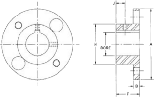 |  | ||||||||||||||
| Size | Max Bore | A | B | F | H | J | STD Set Screw Size | Size | Max Bore | A | B | F | H | J | STD Set Screw Size |
|---|---|---|---|---|---|---|---|---|---|---|---|---|---|---|---|
| 05 | 0.87 | 2.65 | 0.25 | 1.00 | 1.30 | 0.38 | 10-24 UNC | 05 | 1.13 | 2.65 | 0.25 | 1.00 | 1.88 | 0.38 | 10-24 UNC |
| 10 | 1.25 | 3.19 | 0.30 | 1.00 | 1.30 | 0.38 | 1/4-20 UNC | 10 | 1.63 | 3.19 | 0.30 | 1.00 | 2.37 | 0.38 | 1/4-20 UNC |
| 15 | 1.37 | 3.65 | 0.35 | 1.13 | 2.00 | 0.41 | 1/4-20 UNC | 15 | 1.88 | 3.65 | 0.35 | 1.13 | 2.69 | 0.41 | 1/4-20 UNC |
| 20 | 1.62 | 4.08 | 0.35 | 1.32 | 2.40 | 0.50 | 1/4-20 UNC | 20 | 2.13 | 4.08 | 0.35 | 1.32 | 3.13 | 0.50 | 1/4-20 UNC |
| 25 | 2.00 | 4.95 | 0.45 | 1.62 | 2.80 | 0.63 | 5/16-18 UNC | 25 | 2.38 | 4.95 | 0.45 | 1.62 | 3.75 | 0.63 | 5/16-18 UNC |
| 30 | 2.38 | 5.63 | 0.55 | 1.88 | 3.30 | 0.69 | 5/16-18 UNC | 30 | 2.88 | 5.63 | 0.55 | 1.88 | 4.25 | 0.69 | 5/16-18 UNC |
| 35 | 2.88 | 6.63 | 0.55 | 2.25 | 4.15 | 0.88 | 1/2-13 UNC | 35 | 3.75 | 6.63 | 0.55 | 2.25 | 5.25 | 0.88 | 1/2-13 UNC |
| 40 | 3.25 | 7.64 | 0.65 | 2.50 | 4.65 | 0.94 | 1/2-13 UNC | 40 | 4.00 | 7.64 | 0.65 | 2.50 | 6.02 | 0.94 | 1/2-13 UNC |
| 45 | 3.75 | 8.43 | 0.65 | 3.00 | 5.40 | 1.20 | 1/2-13 UNC | 45 | 4.63 | 8.43 | 0.65 | 3.00 | 6.75 | 1.20 | 1/2-13 UNC |
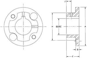
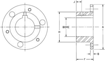
QD Bored HubsMaterial class A or B only - available from stock | Hubs for Taper Lock BushingsAvailable MTO only | ||||||||||||||||
 |  | ||||||||||||||||
| CPLG SIZE | BUSH SIZE | BUSH TQ. LB*IN | MAX BORE | B | C | F | H | BOLT SIZE UNC | CPLG SIZE | REGULAR MOUNT | REVERSE MOUNT | ||||||
|---|---|---|---|---|---|---|---|---|---|---|---|---|---|---|---|---|---|
| BUSH SIZE | BUSH TQ. LB*IN | MAX BORE | F | BUSH SIZE | BUSH TQ. LB*IN | MAX BORE | F | ||||||||||
| 15 | JA | 1000 | 1-1/4 | 1.17 | 1.00 | 0.56 | 2.00 | #10 | 15 | N/A | --- | --- | --- | 1108 | 1300 | 1.12 | 0.87 |
| 20 | JA | 1000 | 1-1/4 | 1.17 | 1.00 | 0.56 | 2.40 | #10 | 20 | 1108 | 1300 | 1.12 | 0.87 | 1215 | 3550 | 1.25 | 1.50 |
| 25 | SH | 3500 | 1-11/16 | 1.50 | 1.25 | 0.75 | 2.80 | 1/4 | 25 | 1215 | 3550 | 1.25 | 1.50 | 1310 | 3850 | 1.37 | 1.00 |
| 30 | SD | 5000 | 2 | 2.06 | 1.81 | 1.25 | 3.30 | 1/4 | 30 | 1310 | 3850 | 1.37 | 1.00 | 1615 | 4300 | 1.62 | 1.50 |
| 35 | SK | 7000 | 2-5/8 | 2.19 | 1.87 | 1.25 | 4.15 | 5/16 | 35 | 2012 | 7150 | 2.00 | 1.25 | 2517 | 11600 | 2.50 | 1.75 |
| 40 | SF | 11000 | 2-15/16 | 2.38 | 2.06 | 1.37 | 4.65 | 3/8 | 40 | 2525 | 11300 | 2.50 | 2.50 | 2525 | 11300 | 2.50 | 2.50 |
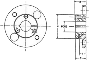
AC/AD Clamping HubsAC Hubs provided without keyway | AL Lock Element HubsThese hubs are ringfeder tapered locking elements | ||||||||||||||
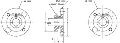 |  | ||||||||||||||
| Size | Max Bore | A | F | G | H | Screw Size | Size | Hub Type | Max Bore | B | F | G | Screw Size | ||
|---|---|---|---|---|---|---|---|---|---|---|---|---|---|---|---|
| AC | AD | Min | Max | ||||||||||||
| 05 | 1.00 | 0.87 | 2.65 | 1.13 | .50 | 2.06 | 1/4-20 UNC | 05 | AJ | 6 | 13 | 1.00 | 1.32 | .32 | 10-32 UNF |
| 10 | 1.00 | 0.87 | 3.19 | 1.18 | .50 | 2.06 | 1/4-20 UNC | AZ | 14 | 19 | 1.00 | 1.42 | .42 | 1/4-28 UNF | |
| 1.50 | 1.25 | 1.36 | .69 | 2.75 | 5/16-18 UNC | 10 | AJ | 12 | 18 | 1.00 | 1.42 | .42 | 1/4-28 UNF | ||
| 15 | 1.00 | 0.87 | 3.65 | 1.27 | .50 | 2.06 | 1/4-20 UNC | AZ | 19 | 30 | 1.00 | 1.42 | .42 | 1/4-28 UNF | |
| 1.75 | 1.37 | 1.46 | .69 | 3.00 | 5/16-18 UNC | 15 | AJ | 12 | 22 | 1.13 | 1.55 | .42 | 1/4-28 UNF | ||
| 20 | 1.31 | 1.00 | 4.08 | 1.32 | .55 | 2.38 | 1/4-20 UNC | AZ | 24 | 35 | 1.13 | 1.55 | .42 | 5/16-24 UNF | |
| 2.12 | 1.62 | 1.52 | .75 | 3.50 | 3/8-16 UNC | 20 | AJ | 22 | 30 | 1.32 | 1.78 | .42 | 1/4-28 UNF | ||
| 25 | 2.13 | 1.62 | 4.95 | 1.62 | .64 | 3.50 | 5/16-18 UNC | AZ | 32 | 42 | 1.32 | 1.83 | .51 | 5/16-24 UNF | |
| 2.50 | 1.87 | 1.86 | .88 | 4.00 | 3/8-16 UNC | 25 | AJ | 22 | 32 | 1.63 | 2.05 | .42 | 1/4-28 UNF | ||
| AZ | 35 | 50 | 1.63 | 2.23 | .60 | 3/8-24 UNF | |||||||||
NOTE: AC and AL Hubs do not carry full torque capacity. Please consult engineering.
6 Bolt Coupling HubsBH series-used on BH, BP, B5, BY series | 8 Bolt Coupling HubsDxx-3 Cast Iron Material, Dxx-3ST Cast Steel Material | |||||||||||||
 |  | |||||||||||||
| Size | Max Bore | A | B | F | H | J | Optional Set Screw Size | Size | Max Bore | A | B | F | H | |
|---|---|---|---|---|---|---|---|---|---|---|---|---|---|---|
| Iron | Steel | |||||||||||||
| 33 | 2.25 | 4.69 | 0.30 | 1.75 | 3.14 | 0.88 | 1/4-20 UNC | 22 | 2.25 | – | 6.00 | 0.53 | 2.50 | 3.88 |
| 38 | 3.00 | 5.87 | 0.35 | 2.25 | 4.13 | 1.13 | 3/8-16 UNC | 26 | 2.62 | – | 6.87 | 0.62 | 2.88 | 4.50 |
| 43 | 3.25 | 6.70 | 0.42 | 2.50 | 4.63 | 1.25 | 3/8-16 UNC | 31 | 3.12 | – | 8.12 | 0.69 | 3.38 | 5.50 |
| 48 | 3.75 | 7.50 | 0.40 | 2.75 | 5.40 | 1.50 | 1/2-13 UNC | 35 | 3.62 | – | 9.12 | 0.88 | 3.75 | 6.12 |
| 53 | 3.88 | 7.87 | 0.55 | 2.88 | 5.65 | 1.44 | 1/2-13 UNC | 37 | 3.75 | – | 10.06 | 0.88 | 4.00 | 6.50 |
| 58 | 4.25 | 9.00 | 0.65 | 3.25 | 6.22 | 1.63 | 1/2-13 UNC | 42 | 4.25 | 4.50 | 11.00 | 1.00 | 4.25 | 7.00 |
| 63 | 4.88 | 10.00 | 0.65 | 3.38 | 7.14 | 1.69 | 3/4-10 UNC | 45 | 4.50 | 4.75 | 11.87 | 1.13 | 4.50 | 7.43 |
| 68 | 5.00 | 10.75 | 0.75 | 3.75 | 7.33 | 1.88 | 3/4-10 UNC | 50 | 5.12 | 5.50 | 13.43 | 1.25 | 5.00 | 9.50 |
| 73 | 5.25 | 12.50 | 1.00 | 5.13 | 7.80 | 2.50 | 3/4-10 UNC | 55 | 5.62 | 6.25 | 15.00 | 1.25 | 5.50 | 9.50 |
| 78 | 6.50 | 15.05 | 1.15 | 6.38 | 9.50 | 3.12 | 3/4-10 UNC | 60 | 6.50 | 7.12 | 16.75 | 1.44 | 6.25 | 10.50 |
| 70 | 7.00 | 7.87 | 18.93 | 1.75 | 7.00 | 11.75 | ||||||||
| 75 | 7.75 | 8.75 | 20.62 | 1.75 | 7.25 | 13.00 | ||||||||
| 80 | 8.00 | 9.12 | 22.37 | 2.09 | 7.75 | 13.75 | ||||||||
| 85 | 8.50 | 9.62 | 23.75 | 2.13 | 8.25 | 14.50 | ||||||||
| 92 | 10.00 | 11.00 | 25.75 | 2.62 | 9.00 | 15.87 | ||||||||
All dimensions are rounded to the nearest fractional size for identification purposes. | |||||||
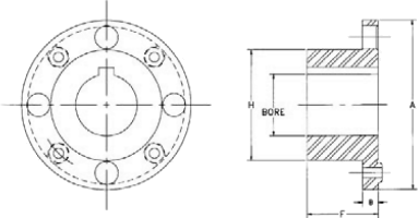
4 BOLT DISCS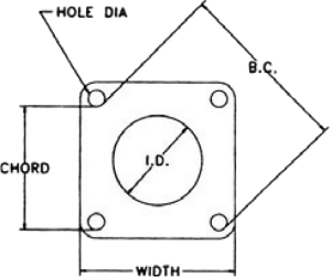 | Size | Width | I.D. | Hole Dia | B.C. Dia | Chord | Disc Set Thickness |
|---|---|---|---|---|---|---|---|
| 05 | 1-13/16 | 1 | 1/4 | 1-7/8 | 1-5/16 | 0.06 | |
| 10 | 2-3/16 | 1-3/16 | 1/4 | 2-3/8 | 1-5/8 | 0.09 | |
| 15 | 2-9/16 | 1-1/4 | 5/16 | 2-5/8 | 1-7/8 | 0.12 | |
| 20 | 2-13/16 | 1-5/8 | 5/16 | 3-1/8 | 2-3/16 | 0.14 | |
| 25 | 3-9/6 | 1-3/4 | 7/16 | 3-3/4 | 2-5/8 | 0.15 | |
| 30 | 4 | 2-1/16 | 1/2 | 4-1/4 | 3 | 0.18 | |
| 35 | 4-3/4 | 2-3/4 | 1/2 | 5-1/4 | 3-3/4 | 0.28 | |
| 40 | 5-1/2 | 3 | 5/8 | 6 | 4-1/4 | 0.30 | |
| 45 | 6-1/16 | 3-1/2 | 5/8 | 6-3/4 | 4-3/4 | 0.40 | |
| 50 | 7 | 4 | 3/4 | 7-3/4 | 5-1/2 | 0.43 | |
| 55 | 7-3/4 | 4-1/4 | 1 | 8-1/2 | 6 | 0.51 | |
6 BOLT DISCS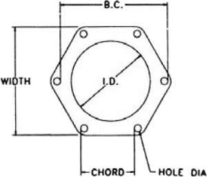 | Size | Width | I.D. | Hole Dia | B.C. Dia | Chord | Disc Set Thickness |
| 33 | 3-3/4 | 2-3/4 | 1/4 | 3-3/4 | 1-7/8 | 0.10 | |
| 38 | 4-13/16 | 3-9/16 | 5/16 | 4-7/8 | 2-7/16 | 0.13 | |
| 43 | 5-11/6 | 3-15/16 | 7/16 | 5-9/16 | 2-7/8 | 0.16 | |
| 48 | 6-3/8 | 4-5/8 | 7/16 | 6-3/8 | 3-3/16 | 0.19 | |
| 53 | 6-3/4 | 4-3/4 | 1/2 | 6-5/8 | 3-5/16 | 0.24 | |
| 58 | 7-3/4 | 5-1/4 | 5/8 | 7-7/16 | 3-3/4 | 0.25 | |
| 63 | 8-1/2 | 6 | 5/8 | 8-3/8 | 4-3/16 | 0.30 | |
| 68 | 9-1/4 | 6-1/4 | 3/4 | 9-15/16 | 5 | 0.34 | |
| 73 | 10-5/8 | 6-5/8 | 1 | 10 | 5 | 0.44 | |
| 78 | 13-9/16 | 7-7/8 | 1-1/4 | 12 | 6 | 0.54 | |
8 BOLT DISCS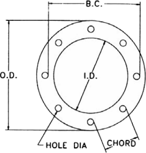 | Size | Width | I.D. | Hole Dia | B.C. Dia | Chord | Disc Set Thickness |
| 22 | 5-5/8 | 3-7/8 | 5/16 | 4-3/4 | 1-13/16 | 0.17 | |
| 26 | 6-9/16 | 4-7/16 | 13/32 | 5-1/2 | 2-1/8 | 0.23 | |
| 31 | 7-3/4 | 5-1/4 | 15/32 | 6-1/2 | 2-1/2 | 0.25 | |
| 35 | 8-5/8 | 5-3/4 | 17/32 | 7-1/4 | 2-3/4 | 0.29 | |
| 37 | 9-5/8 | 6-5/16 | 5/8 | 8 | 3-1/16 | 0.31 | |
| 42 | 10-1/2 | 6-3/4 | 11/16 | 8-5/8 | 3-5/16 | 0.31 | |
| 45 | 11-1/4 | 7-1/4 | 3/4 | 9-1/4 | 3-1/2 | 0.37 | |
| 50 | 12-13/16 | 8-1/2 | 7/8 | 10-1/2 | 4 | 0.46 | |
| 55 | 14-3/8 | 9 | 1 | 11-3/4 | 4-1/2 | 0.54 | |
| 60 | 15-15/16 | 9-15/16 | 1-1/8 | 13 | 5 | 0.59 | |
| 70 | 18-1/8 | 11-1/8 | 1-5/16 | 14-3/4 | 5-5/8 | 0.78 | |
| 75 | 19-3/4 | 12 | 1-7/16 | 16 | 6-1/8 | 0.80 | |
| 80 | 21-7/16 | 13-1/8 | 1-9/16 | 17-3/8 | 6-5/8 | 0.81 | |
| 85 | 22-7/8 | 14 | 1-3/4 | 18-1/2 | 7-1/8 | 0.87 | |
| 92 | 24-7/8 | 15 | 1-7/8 | 20 | 7-5/8 | 1.00 | |
AGMA 9002--A86-BORES AND KEYWAYS FOR FLEXIBLE COUPLINGS
AGMA 9000-C90-FLEXIBLE COUPLINGS - POTENTIAL UNBALANCED CLASSIFICATION
AGMA514.02-LOAD CLASSIFICATION AND SERVICE FACTORS FOR FLEXIBLE COUPLINGS
AP1610-CENTRIFUGAL PUMPS FOR GENERAL REFINERY SERVICE, 7th Edition-BF and BP series meet the requirements of AP1610, 7th Edition when supplied with interference fit bores. Other coupling series can be altered to comply with AP1610.
NEMA MG1-14.37 AND MG1-21.81-All Form-Flex metal disc couplings meet these standards without limited end float devices.
Certain tables and data in this catalogue were extracted from the reference AGMA standards with the permission of the publisher, the American Gear Manufacturers Associations, 1901 North Meyer Drive, Arlington, VA 22209.
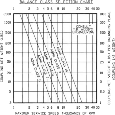 Use this graph to determine the appropriate balance class based on coupling weight and operating speed. The balance classes listed on the graph are for equipment with average sensitivity to coupling unbalance. The user should determine how sensitive the equipment train is to coupling unbalance. Use one balance class higher if your system has higher than average sensitivity to unbalance. Use one balance class lower if your system has lower than average sensitivity to unbalance. Use this guide to check your coupling selection against the recommended balance class for your operating conditions.
The following factors should be considered when determining a machine's sensitivity to coupling unbalance.
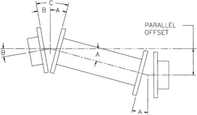 Double flexing metal disc couplings may be used to accommodate angular, parallel and axial misalignment. Single flexing couplings may only be used to accommodate angular and axial misalignment. A metal disc type coupling uses a double hinge effect through two flexible discs and spacer to compensate for parallel offset misalignment between shafts. Parallel misalignment imposes the same angular deflection (A) on each flex disc. Angular misalignment of either connected shaft (B) creates additional angular deflections which are added to the angular offset due to parallel misalignment. The total misalignment angle (C) at the flex disc is equal to the angular offset misalignment (B). The maximum misalignment angle (C) should never exceed the rated misalignment capacity of the coupling type being used. Machinery equipment changes in actual operation and over the life of the equipment. We recommend that the machinery misalignment be set as close to zero as possible when a coupling is installed. We recommend keeping the measured misalignment below 25% of the rated misalignment capacity of the coupling type used when the machinery is installed and aligned. The remaining coupling misalignment capacity will then be available to accommodate additional misalignment caused by foundation shifts, vibrations, thermal growth or other causes.
| FEATURE | AR, AK, AP, AX, AY | BH, BP, BY, DP* | BF | BA, DA* | A5, A7 | B5 | HFTH | HH, HSH, FSH |
|---|---|---|---|---|---|---|---|---|
| STANDARD BORE FIT | Clearance | Interference | Clearance | Interference | ||||
| SET SCREWS | Standard | Optional | Standard | Optional | ||||
| PULLER HOLES | Optional | Standard | Optional | Standard | Optional | |||
| STANDARD FLEX DISCS | 300 Series Stainless Steel* | Alloy Steel | ||||||
| BALANCE CLASS | AGMA 7 | AGMA 8 | AGMA 9 | AGMA 7 | N/A | N/A | ||
| DYNAMIC BALANCE | Optional | Per TBW Commercial Standard | N/A | |||||
* Alloy steel flex disc is standard for DA and DP series. Stainless steel is optional.
| INCH SIZE | SIZE | KEYWAY SIZE | BORE TOLERANCES | |
|---|---|---|---|---|
| CLEARANCE FIT | INTERFERENCE FIT | |||
| 1/2 | 12 | 1/8 x 1/16 | .500/.501 | --- |
| 5/8 | 58 | 3/16 x 3/32 | .625/.626 | --- |
| 3/4 | 34 | 3/16 x 3/32 | .750/.751 | .7490/.7495 |
| 7/8 | 78 | 3/16 x 3/32 | .875/.876 | .8740/.8745 |
| 15/16 | 15/16 | 1/4 x 1/8 | .9375/.9385 | .9365/.9370 |
| 1 | 1 | 1/4 x 1/8 | 1.000/1.001 | .9990/9995 |
| 1-1/8 | 118 | 1/4 x 1/8 | 1.125/1.126 | 1.1240/1.1245 |
| 1-3/16 | 1316 | 1/4 x 1/8 | 1.1875/1.1885 | 1.1865/1.1870 |
| 1-1/4 | 114 | 1/4 x 1/8 | 1.250/1.251 | 1.2490/1.2495 |
| 1-3/8 | 138 | 5/16 x 5/32 | 1.375/1.376 | 1.3740/1.3745 |
| 1-7/16 | 1716 | 3/8 x 3/16 | 1.4375/1.4385 | 1.4365/1.4370 |
| 1-1/2 | 112 | 3/8 x 3/16 | 1.500/1.501 | 1.4990/1.4995 |
| 1-5/8 | 158 | 3/8 x 3/16 | 1.625/1.626 | 1.623/1.624 |
| 1-3/4 | 134 | 3/8 x 3/16 | 1.750/1.751 | 1.748/1.749 |
| 1-7/8 | 178 | 1/2 x 1/4 | 1.875/1/876 | 1.873/1.874 |
| 1-15/16 | 11516 | 1/2 x 1/4 | 1.9375/1.9385 | 1.9355/1.9365 |
| 2 | 2 | 1/2 x 1/4 | 2.000/2.001 | 1.998/1.999 |
| 2-1/8 | 218 | 1/2 x 1/4 | 2.1250/2.1265 | 2.123/2.124 |
| 2-1/4 | 214 | 1/2 x 1/4 | 2.2500/2.2515 | 2.248/2.249 |
| 2-3/8 | 238 | 5/8 x 5/16 | 2.3750/2.3765 | 2.373/2.374 |
| 2-7/16 | 2716 | 5/8 x 5/16 | 2.4375/2.4390 | 2.4355/2.4365 |
| 2-1/2 | 212 | 5/8 x 5/16 | 2.500/2.5015 | 2.498/2.499 |
| 2-5/8 | 258 | 5/8 x 5/16 | 2.6250/2.6265 | 2.623/2.624 |
| 2-3/4 | 234 | 5/8 x 5/16 | 2.7500/2.7515 | 2.748/2.749 |
| 2-7/8 | 278 | 3/4 x 3/8 | 2.8750/2.8765 | 2.873/2.874 |
| 2-15/16 | 21516 | 3/4 x 3/8 | 2.9375/2.9390 | 2.9355/2.9365 |
| 3 | 3 | 3/4 x 3/8 | 3.000/3.0015 | 2,998/2.999 |
| 3-1/4 | 314 | 3/4 x 3/8 | 3.2500/3.2515 | 3.2470/3.2485 |
| 3-3/8 | 338 | 7/8 x 7/16 | 3.3750/3.3765 | 3.3720/3.3735 |
| 3-1/2 | 312 | 7/8 x 7/16 | 3.5000/3.5015 | 3.4970/3.4985 |
| 3-5/8 | 358 | 7/8 x 7/16 | 3.6250/3.6265 | 3.6220/3.6235 |
| 3-3/4 | 334 | 7/8 x 7/16 | 3.7500/3.7515 | 3.7470/3.7485 |
| 4 | 4 | 1 x 1/2 | 4.000/4.0015 | 3.9970/3.9985 |
| 4-1/4 | 414 | 1 x 1/2 | 4.2500/4.2515 | 4.2465/4.2480 |
| 4-1/2 | 412 | 1 x 1/2 | 4.5000/4.5015 | 4.4965/4.4980 |
| 4-3/4 | 434 | 1-1/4 x 5/8 | 4.7500/4.7515 | 4.7465/4.7480 |
| 5 | 5 | 1-1/4 x 5/8 | --- | 4.9965/4.9980 |
| 5-1/4 | 514 | 1-1/4 x 5/8 | --- | 5.2460/5.2475 |
| 5-1/2 | 512 | 1-1/4 x 5/8 | --- | 5.4960/5.4975 |
| 5-3/4 | 534 | 1-1/2 x 3/4 | --- | 5.7460/5.7475 |
| METRIC SIZE | SIZE CODE | KEYWAY SIZE | BORE TOLERANCE | KEYWAY TOLERANCES | |||
|---|---|---|---|---|---|---|---|
| CLEARANCE FIT | |||||||
| 6 | 6mm | 2 x 1 | .236/.237 | WIDTH | English | + .002”/–0.000” | |
| 8 | 8mm | 2 x 1 | .315/.316 | Metric | + .001”/–0.000” | ||
| 10 | 10mm | 3 x 1.4 | .394/.395 | HEIGHT AT SIDE OF KW | Bore < = 3.375” | + .015”/–0.000” | |
| 12 | 12mm | 4 x 1.8 | .4725/.4735 | Bore > 3.375” | + .020”/–0.000” | ||
| 13 | 13mm | 5 x 2.3 | .512/.513 | 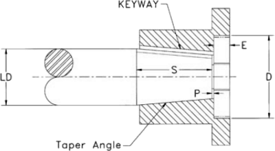 | |||
| 14 | 14mm | 5 x 2.3 | .551/.552 | ||||
| 15 | 15mm | 5 x 2.3 | .591/.592 | ||||
| 16 | 16mm | 5 x 2.3 | .630/.631 | ||||
| 18 | 18mm | 6 x 2.8 | .709/.710 | ||||
| 20 | 20mm | 6 x 2.8 | .7875/.7885 | ||||
| 22 | 22mm | 6 x 2.8 | .866/.867 | ||||
| 24 | 24mm | 8 x 3.3 | .945/.946 | ||||
| 25 | 25mm | 8 x 3.3 | .984/.985 | ||||
| 28 | 28mm | 8 x 3.3 | 1.1025/1.1035 | ||||
| 30 | 30mm | 8 x 3.3 | 1.181/1.182 | ||||
| 32 | 32mm | 10 x 3.3 | 1.260/1.261 | ||||
| 35 | 35mm | 10 x 3.3 | 1.378/1.379 | ||||
| 38 | 38mm | 10 x 3.3 | 1.496/1.497 | ||||
| 40 | 40mm | 12 x 3.3 | 1.575/1.576 | ||||
| 45 | 45mm | 14 x 3.8 | 1.772/1.773 | ||||
| 48 | 48mm | 14 x 3.8 | 1.890/1.891 | ||||
| 50 | 50mm | 14 x 3.8 | 1.969/1.970 | ||||
| 55 | 55mm | 16 x 4.3 | 2.1655/2.1670 | ||||
| 60 | 60mm | 18 x 4.4 | 2.3620/2.3635 | ||||
| 65 | 65mm | 18 x 4.4 | 2.5590/2.5605 | ||||
| 70 | 70mm | 20 x 4.9 | 2.7560/2.7575 | ||||
| 75 | 75mm | 20 x 4.9 | 2.9530/2.9545 | ||||
| 80 | 80mm | 22 x 5.4 | 3.1500/3.1515 | ||||
| 85 | 85mm | 22 x 5.4 | 3.3465/3.3480 | ||||
| 90 | 90mm | 25 x 5.4 | 3.5435/3.5450 | ||||
| 95 | 95mm | 25 x 5.4 | 3.7400/3.9385 | ||||
| 100 | 100mm | 28 x 6.4 | 3.9370/3.9385 | ||||
| 110 | 110mm | 28 x 6.4 | 4.3310/4.3325 | ||||
Bore tolerances in inches
Keyway sizes in mm
Please provide the following information for taper bore hubs:
The AR series coupling accommodates angular and axial misalignment only. Single couplings may be used in pairs to support a clutch, brake or other power transmission component in a floating shaft arrangement, or to support a component that is supported by a self-aligning bearing. The AR coupling consists of two hubs and one set of standard hardware, including stainless steel flex discs.
| Rated Misalignment: 1.0 Deg/Disc | |||||||
| Hub Options | Coupling Consists of: 2-Hubs-Example-AJ35A x 1-3/8 1-Flex Assembly-Example-A35RKA This coupling is sold as components | Material Classes | Flex Assy Part No. | ||||
|---|---|---|---|---|---|---|---|
| Hub Type | Size | Class | Size | ||||
| AJ -STANDARD | 05-45 | A | 05-45 | AxxRKA | |||
| AZ OVERSIZE | 05-45 | B | 05-45 | AxxRKA | |||
| QD BUSHING MOUNT | 15-40 | C | 15-45 | AxxRKE | |||
| AC/AD CLAMP | 05-25 | E | 15-45 | AxxRKE | |||
| AL LOCK ELEMENT | 05-25 | xx = Size | |||||
| Size | Dimensions in Inches | Free End Float +/- Inch | |||||||
|---|---|---|---|---|---|---|---|---|---|
| Max Bore | A | B | D DBSE | F | H | J | |||
| AJ | AZ | ||||||||
| 05 | 0.87 | 1.13 | 2.65 | 2.24 | 0.24 | 1.00 | 1.30 | 0.54 | 0.015 |
| 10 | 1.25 | 1.63 | 3.19 | 2.27 | 0.27 | 1.00 | 1.80 | 0.59 | 0.020 |
| 15 | 1.37 | 1.88 | 3.65 | 2.58 | 0.32 | 1.13 | 2.00 | 0.88 | 0.021 |
| 20 | 1.62 | 2.13 | 4.08 | 2.98 | 0.34 | 1.32 | 2.40 | 0.79 | 0.027 |
| 25 | 2.00 | 2.38 | 4.95 | 3.69 | 0.45 | 1.62 | 2.80 | 1.00 | 0.030 |
| 30 | 2.38 | 2.88 | 5.63 | 4.23 | 0.47 | 1.88 | 3.30 | 1.14 | 0.032 |
| 35 | 2.88 | 3.75 | 6.63 | 5.05 | 0.55 | 2.25 | 4.15 | 0.97 | 0.042 |
| 40 | 3.25 | 4.00 | 7.64 | 5.60 | 0.60 | 2.50 | 4.65 | 1.30 | 0.050 |
| 45 | 3.75 | 4.63 | 8.43 | 6.85 | 0.85 | 3.00 | 5.40 | 0.77 | 0.060 |
| * Dimensions shown are for AJ hubs unless otherwise specified | |||||||||
| Size | HP per 100 RPM | Rated Torque (LB. IN.) | Peak O/L Torque (LB. IN.) | Agma 7 Max RPM | Max Radial Load (LBS.) | Weight (LBS.) | WR2 (LB. IN.2) | TQ/RAD X106 (LB. IN./RAD) |
|---|---|---|---|---|---|---|---|---|
| 1.0 S.F | ||||||||
| 05 | 0.48 | 300 | 600 | 8,500 | 34 | 1.24 | 0.96 | 0.28 |
| 10 | 1.27 | 800 | 1,600 | 7,500 | 56 | 1.96 | 2.35 | 0.84 |
| 15 | 2.50 | 1,575 | 3,150 | 6,700 | 125 | 2.98 | 4.62 | 1.47 |
| 20 | 3.49 | 2,200 | 4,400 | 6,200 | 183 | 4.07 | 7.48 | 2.11 |
| 25 | 6.03 | 3,800 | 7,600 | 5,500 | 275 | 7.01 | 20.4 | 3.62 |
| 30 | 11.00 | 6,930 | 13,860 | 5,000 | 400 | 10.8 | 41.5 | 5.91 |
| 35 | 18.00 | 11,340 | 22,680 | 4,400 | 600 | 17.2 | 88.3 | 11.0 |
| 40 | 29.00 | 18,270 | 36,540 | 4,000 | 850 | 25.6 | 178 | 17.0 |
| 45 | 48.00 | 30,240 | 60,480 | 3,700 | 1000 | 292 | 292 | 25.8 |
| Note: 1) Weight, WR2 and torsional stiffness values shown are for AJ hubs at maximum bore size. | ||||||||
The BH series coupling accommodates angular and axial misalignment only. Single couplings may be used in pairs to support a clutch, brake or other power transmission component in a floating shaft arrangement, or to support a component that is supported by a self-aligning bearing. The BH coupling consists of two hubs and one set of standard hardware, including stainless steel flex discs.
| Rated Misalignment: 0.7 Deg/Disc | |||||||
| Hub Types | Sizes | Coupling Consists of: 2-Hubs-Example-BH48A x 3” 1-Flex Assembly-Example-B048RKA This coupling is sold as components | Material Classes | Flex Assy Part No. | |||
|---|---|---|---|---|---|---|---|
| BH | 33-78 | Class | Size | ||||
| A | 33-78 | BOxxRKA | |||||
| B | 33-78 | BOxxRKA | |||||
| C | 38-63 | BOxxRKE | |||||
| E | MTO 38-63 | BOxxRKE | |||||
| xx = Size | |||||||
| Size | Dimensions in Inches | |||||
|---|---|---|---|---|---|---|
| Max Bore | A | B | D DBSE | F | H | |
| 33 | 2.25 | 4.69 | 3.79 | 0.29 | 1.75 | 3.14 |
| 38 | 3.00 | 5.87 | 4.84 | 0.34 | 2.25 | 4.13 |
| 43 | 3.25 | 6.70 | 5.47 | 0.47 | 2.50 | 4.63 |
| 48 | 3.75 | 7.50 | 6.00 | 0.50 | 2.75 | 5.40 |
| 53 | 3.88 | 7.87 | 6.28 | 0.52 | 2.88 | 5.65 |
| 58 | 4.25 | 9.00 | 7.06 | 0.56 | 3.25 | 6.22 |
| 63 | 4.88 | 10.00 | 7.36 | 0.60 | 3.38 | 7.14 |
| 68 | 5.00 | 10.75 | 8.35 | 0.85 | 3.75 | 7.33 |
| 73 | 5.25 | 12.50 | 11.26 | 1.00 | 5.13 | 7.80 |
| 78 | 6.50 | 15.05 | 13.70 | 0.94 | 6.38 | 9.50 |
| Size | HP per 100 RPM | Rated Torque (LB. IN.) | Peak O/L Torque (LB. IN.) | Agma 7 Max RPM | Max Radial Load (LBS.) | Weight (LBS.) | WR2 (LB. IN.2) | TQ/RAD X106 (LB. IN./RAD) | Free End Float +/- Inch |
|---|---|---|---|---|---|---|---|---|---|
| 1.0 S.F | |||||||||
| 33 | 4.84 | 3,050 | 6,100 | 8,400 | 150 | 5.76 | 14.5 | 4.57 | 0.03 |
| 38 | 10.08 | 6,350 | 112,500 | 7,500 | 240 | 11.4 | 46.6 | 9.41 | 0.04 |
| 43 | 19.84 | 12,500 | 25,000 | 6,800 | 420 | 17.3 | 91.7 | 17.8 | 0.05 |
| 48 | 26.98 | 17,000 | 34,000 | 6,500 | 655 | 25.2 | 171 | 35.5 | 0.06 |
| 53 | 38.10 | 24,000 | 48,000 | 6,000 | 720 | 29.8 | 226 | 29.8 | 0.06 |
| 58 | 53.97 | 34,000 | 68,000 | 5,500 | 930 | 45.4 | 443 | 50.0 | 0.06 |
| 63 | 76.19 | 48,000 | 96,000 | 5,200 | 1,125 | 58.4 | 715 | 76.6 | 0.07 |
| 68 | 114.29 | 72,000 | 144,000 | 4,800 | 1,530 | 73.4 | 984 | 96.7 | 0.07 |
| 73 | 198.41 | 125,000 | 250,000 | 4,200 | 2,190 | 115 | 2,050 | 139 | 0.08 |
| 78 | 369.84 | 233,000 | 466,000 | 3,700 | 4,600 | 212 | 5,340 | 251 | 0.08 |
| Note: 1) Weight, WR2 and torsional stiffness values shown for BH hubs at maximum bore size. | |||||||||
The HH series is designed for high torque, low speed applications, Hubs are cast of iron or steel. Flex discs are high strength alloy steel. Stainless steel flex discs are optional. Dynamic balancing for higher speed operation is not recommended. Single plane balancing of individual hubs is available.
| Rated Misalignment: 0.7 Deg/Disc | ||||
| Hub Options | Ordering: HH Series couplings are sold as complete assemblies. Please specify hub type, bore sizes. and flex disc materials. A coupling will be configured to meet your specification. | |||
|---|---|---|---|---|
| Hub Types | Sizes | |||
| C.I. | 26-160 | |||
| STL | 31-160 | |||
| Size | Dimensions in Inches | ||||||
|---|---|---|---|---|---|---|---|
| Max Bore | A | B | D DBSE | F | H | ||
| Iron | Steel | ||||||
| 22 | 2.25 | - | 6.00 | 5.43 | 0.43 | 2.50 | 3.87 |
| 26 | 2.62 | - | 6.87 | 6.29 | 0.53 | 2.88 | 4.50 |
| 31 | 3.12 | 3.25 | 8.12 | 7.38 | 0.62 | 3.38 | 5.50 |
| 35 | 3.62 | 3.81 | 9.12 | 8.16 | 0.66 | 3.75 | 6.12 |
| 37 | 3.75 | 4.19 | 10.06 | 8.81 | 0.81 | 4.00 | 6.50 |
| 42 | 4.25 | 4.50 | 11.00 | 9.31 | 0.81 | 4.25 | 7.00 |
| 45 | 4.50 | 4.75 | 11.87 | 9.87 | 0.87 | 4.50 | 7.43 |
| 50 | 5.12 | 5.50 | 13.43 | 11.06 | 1.06 | 5.00 | 9.50 |
| 55 | 5.62 | 6.25 | 15.00 | 12.25 | 1.25 | 5.50 | 9.50 |
| 60 | 6.50 | 7.12 | 16.75 | 13.84 | 1.34 | 6.25 | 10.50 |
| 70 | 7.00 | 7.87 | 18.93 | 15.50 | 1.50 | 7.00 | 11.75 |
| 75 | 7.75 | 8.75 | 20.62 | 16.05 | 1.55 | 7.25 | 13.00 |
| 80 | 8.00 | 9.12 | 22.37 | 17.06 | 1.56 | 7.75 | 13.75 |
| 85 | 8.50 | 9.62 | 23.75 | 18.12 | 1.62 | 8.25 | 14.50 |
| 92 | 10.00 | 11.00 | 25.75 | 19.75 | 1.75 | 9.00 | 15.87 |
| 105 | 10.50 | 12.00 | 29.25 | 22.75 | 1.75 | 10.50 | 20.00 |
| 160 | 16.00 | 17.00 | 33.50 | 26.25 | 2.25 | 12.00 | 24.00 |
| Size | HP per 100 RPM | Rated Torque (LB. IN.) | Peak O/L Torque (LB. IN.) | Agma 7 Max RPM | Max Radial Load (LBS.) | Weight (LBS.) | WR2 (LB. IN.2) | TQ/RAD X106 (LB. IN./RAD) | Free End Float +/- Inch |
|---|---|---|---|---|---|---|---|---|---|
| 1.0 S.F | |||||||||
| 22 | 15.08 | 9,500 | 14,250 | 3,800 | 338 | 17 | 62 | 12.7 | 0.018 |
| 26 | 25.40 | 16,000 | 24,000 | 3,300 | 570 | 26 | 129 | 22.1 | 0.022 |
| 31 | 38.10 | 24,000 | 36,000 | 2,800 | 700 | 43 | 304 | 36.4 | 0.026 |
| 35 | 69.84 | 44,000 | 66,000 | 2,600 | 930 | 61 | 557 | 52.8 | 0.028 |
| 37 | 95.24 | 60,000 | 90,000 | 2,500 | 1,170 | 77 | 820 | 69.6 | 0.031 |
| 42 | 115.87 | 73,000 | 109,500 | 2,400 | 1,300 | 95 | 1,250 | 84 | 0.034 |
| 45 | 157.14 | 99,000 | 148,500 | 2,250 | 1,700 | 115 | 1,810 | 106 | 0.036 |
| 50 | 203.17 | 128,000 | 192,000 | 2,000 | 2,250 | 163 | 3,290 | 147 | 0.041 |
| 55 | 300.00 | 189,000 | 283,500 | 1,800 | 3,200 | 228 | 5,570 | 243 | 0.046 |
| 60 | 414.29 | 261,000 | 391,500 | 1,600 | 4,000 | 328 | 10,300 | 349 | 0.051 |
| 70 | 658.73 | 415,000 | 622,500 | 1,400 | 6,100 | 451 | 18,200 | 482 | 0.058 |
| 75 | 846.03 | 533,000 | 799,500 | 1,300 | 6,900 | 588 | 27,400 | 682 | 0.062 |
| 80 | 1,087.30 | 685,000 | 1,027,500 | 1,200 | 7,500 | 732 | 42,100 | 779 | 0.068 |
| 85 | 1,315.87 | 829,000 | 1,243,500 | 1,100 | 8,700 | 840 | 54,700 | 911 | 0.070 |
| 92 | 1,650.79 | 1,040,000 | 1,560,000 | 1,000 | 11,100 | 1,160 | 89,400 | 1220 | 0.078 |
| 105 | 1,984.13 | 1,250,000 | 1,875,000 | 1,000 | 8,460 | 1,780 | 160,000 | 3200 | 0.085 |
| 160 | 3,174.60 | 2,000,000 | 3,000,000 | 900 | 11,300 | 2,310 | 325,000 | 5140 | 0.125 |
| Note: 1) Weight, WR2 and torsional stiffness values shown are for Cast Iron hubs at maximum bore size. | |||||||||
(General Use)
The AX series close coupling is made up of two hubs, a steel spacer block, two stainless flex discs and AX hardware. A special bolting arrangement supports the spacer between the flex discs. The AX is an economical design that is well suited to many general purpose applications. The AX accommodates close shaft separations when it is installed with the shafts extending through the flex discs into the centre of the coupling. The shaft diameter must be less than the flex disc I.D. listed in the dimensional table.
| AD HUB SHOWN | Rated Misalignment: 1.0 Deg/Disc | ||||||
| Hub Options | Coupling Consists of: 2-Hubs-Example-AJ20A x 1-1/2” 1-Space Assembly-Example-A x 20SAA This coupling is sold as components | Material Classes | Flex Assy Part No. | ||||
|---|---|---|---|---|---|---|---|
| Hub Type | Size | Class | Size | ||||
| AJ - STANDARD | 05-45 | A | 05-45 | AxxSAA | |||
| AZ OVERSIZE | 05-45 | B | 05-45 | AxxSAB | |||
| QD BUSHING MOUNT | 15-40 | C | N/A | N/A | |||
| AC/AD CLAMP | 05-25 | E | N/A | N/A | |||
| AL LOCK ELEMENT | 05-25 | xx = Size | |||||
| Size | Dimensions in Inches* | ||||||||||
|---|---|---|---|---|---|---|---|---|---|---|---|
| Max Bore | A | B | DBSE | F | G | H | J | Disc I.D.** | |||
| AJ | AZ | Dmin | Dmax | ||||||||
| 05 | 0.87 | 1.13 | 2.65 | 3.34 | 0.38 | 1.34 | 1.00 | 0.48 | 1.30 | 1.68 | 1.00 |
| 10 | 1.25 | 1.63 | 3.19 | 3.40 | 0.44 | 1.40 | 1.00 | 0.48 | 1.80 | 1.79 | 1.17 |
| 15 | 1.37 | 1.88 | 3.65 | 3.80 | 0.63 | 1.54 | 1.13 | 0.44 | 2.00 | 1.85 | 1.28 |
| 20 | 1.62 | 2.13 | 4.08 | 4.22 | 0.63 | 1.58 | 1.32 | 0.48 | 2.40 | 1.66 | 1.65 |
| 25 | 2.00 | 2.38 | 4.95 | 5.36 | 0.75 | 2.12 | 1.62 | 0.69 | 2.80 | 2.39 | 1.78 |
| 30 | 2.38 | 2.88 | 5.63 | 6.30 | 1.00 | 2.54 | 1.88 | 0.77 | 3.30 | 3.18 | 2.01 |
| 35 | 2.88 | 3.75 | 6.63 | 7.17 | 1.13 | 2.67 | 2.25 | 0.77 | 4.15 | 2.81 | 2.71 |
| 40 | 3.25 | 4.00 | 7.64 | 8.30 | 1.13 | 3.30 | 2.50 | 1.08 | 4.65 | 4.03 | 3.00 |
| 45 | 3.75 | 4.63 | 8.43 | 9.55 | 1.50 | 3.55 | 3.00 | 1.03 | 5.40 | 3.28 | 3.51 |
| * Dimensions shown are for AJ hubs unless otherwise specified ** Shaft I.D. must be less than disc I.D. in order to extend shafts into coupling to eet Dmin dimension. | |||||||||||
| Size | HP per 100 RPM | Rated Torque (LB. IN.) | Peak O/L Torque (LB. IN.) | Agma 7 Max RPM | Weight (LBS.) | WR2 (LB. IN.2) | TQ/RAD X106 (LB. IN./RAD) | Free End Float +/- Inch |
|---|---|---|---|---|---|---|---|---|
| 1.0 S.F | ||||||||
| 05 | 0.48 | 300 | 450 | 8,500 | 1.63 | 1.26 | 0.04 | 0.030 |
| 10 | 1.27 | 800 | 1,200 | 7,500 | 2.48 | 2.90 | 0.06 | 0.040 |
| 15 | 2.50 | 1,575 | 2,363 | 6,700 | 3.84 | 5.80 | 0.21 | 0.042 |
| 20 | 3.49 | 2,200 | 3,300 | 6,200 | 5.10 | 9.16 | 0.25 | 0.055 |
| 25 | 6.03 | 3,800 | 5,700 | 5,500 | 9.13 | 26.1 | 0.56 | 0.060 |
| 30 | 11.00 | 6,930 | 10,395 | 5,000 | 13.8 | 51.7 | 0.79 | 0.065 |
| 35 | 18.00 | 11,340 | 17,010 | 4,400 | 21.1 | 108 | 1.48 | 0.085 |
| 40 | 29.00 | 18,270 | 27,405 | 4,000 | 32.0 | 222 | 1.68 | 0.100 |
| 45 | 48.00 | 30,240 | 45,360 | 3,700 | 44.4 | 365 | 4.54 | 0.120 |
| Note: 1) Weight, WR2 and torsional stiffness values shown are for AJ hubs at maximum bore size. | ||||||||
(General Use - Shorter Bolt Removal)
The AA series close coupling is made up of two hubs, a cast iron block type spacer and two sets of standard hardware. Stainless steel flex discs are standard. The AA accommodates close shaft separations when it is installed with the shafts extending through the flex discs into the centre of the coupling. The shaft diameter must be less than the flex disc I.D. listed in the dimensional table. This coupling is recommended when the bolt removal length (J) makes the AX coupling impractical. Special machined steel block spacers are also available in several sizes.
| Rated Misalignment: 1.0 Deg/Disc | |||||||
| Hub Options | Coupling Consists of: 2-Hubs-Example–AJ35A x 2” 1-Space Assembly -Example–AA35SAA This coupling is sold as components | Material Classes | Spacer Assembly Part No. | ||||
|---|---|---|---|---|---|---|---|
| Hub Type | Size | Class | Size | ||||
| AJ - Standard | 05-45 | A | 05-45 | AAxxSAA | |||
| AZ Oversize | 05-45 | B | 05-45 | AAxxSAB | |||
| QD Bushing Mount | 15-40 | C | 15-45 | AAxxSAC | |||
| AC/AD Clamp | 05-25 | E | N/A | N/A | |||
| AL Lock Element | 05-25 | xx = Size | |||||
| Size | Dimensions in Inches* | ||||||||||
|---|---|---|---|---|---|---|---|---|---|---|---|
| Max Bore | A | B | DBSE | F | G | H | J | Disc I.D. ** | |||
| AJ | AZ | Dmin | Dmax | ||||||||
| 05 | 0.87 | 1.13 | 2.65 | 3.23 | 0.25 | 1.23 | 1.00 | 0.24 | 1.30 | 0.54 | 1.00 |
| 10 | 1.25 | 1.63 | 3.19 | 3.73 | 0.25 | 1.73 | 1.00 | 0.27 | 1.80 | 0.56 | 1.17 |
| 15 | 1.37 | 1.88 | 3.65 | 3.82 | 0.31 | 1.56 | 1.13 | 0.32 | 2.00 | 0.88 | 1.28 |
| 20 | 1.62 | 2.13 | 4.08 | 4.38 | 0.41 | 1.74 | 1.32 | 0.34 | 2.40 | 0.79 | 1.65 |
| 25 | 2.00 | 2.38 | 4.95 | 5.26 | 0.41 | 2.02 | 1.62 | 0.45 | 2.80 | 1.00 | 1.78 |
| 30 | 2.38 | 2.88 | 5.63 | 6.24 | 0.56 | 2.48 | 1.88 | 0.47 | 3.30 | 1.14 | 2.01 |
| 35 | 2.88 | 3.75 | 6.63 | 6.91 | 0.66 | 2.41 | 2.25 | 0.55 | 4.15 | 0.97 | 2.71 |
| 40 | 3.25 | 4.00 | 7.64 | 7.70 | 0.75 | 2.70 | 2.50 | 0.60 | 4.65 | 1.30 | 3.00 |
| 45 | 3.75 | 4.63 | 8.43 | 9.26 | 0.88 | 3.26 | 3.00 | 0.85 | 5.40 | 0.77 | 3.51 |
| * Dimensions shown are for AJ hubs unless otherwise specified ** Shaft I.D. must be less than disc I.D. in order to extend shafts into coupling to meet Dmin dimension. | |||||||||||
| Size | HP per 100 RPM | Rated Torque (LB. IN.) | Peak O/L Torque (LB. IN.) | Max RPM | Weight (LBS.) | WR2 (LB. IN.2) | TQ/RAD X106 (LB. IN./RAD) | Free End Float +/- Inch |
|---|---|---|---|---|---|---|---|---|
| 1.0 S.F | ||||||||
| 05 | 0.48 | 300 | 450 | 3,600 | 1.76 | 1.40 | 0.06 | 0.030 |
| 10 | 1.27 | 800 | 1,200 | 3,500 | 2.77 | 3.35 | 0.10 | 0.040 |
| 15 | 2.50 | 1,575 | 2,363 | 3,450 | 4.24 | 6.66 | 0.26 | 0.042 |
| 20 | 3.49 | 2,200 | 3,300 | 3,350 | 5.48 | 10.2 | 0.25 | 0.055 |
| 25 | 6.03 | 3,800 | 5,700 | 3,200 | 9.81 | 29.4 | 0.62 | 0.060 |
| 30 | 11.00 | 6,930 | 10,395 | 3,000 | 15.0 | 59 | 0.94 | 0.065 |
| 35 | 18.00 | 11,340 | 17,010 | 2,800 | 22.4 | 121 | 1.44 | 0.085 |
| 40 | 29.00 | 18,270 | 27,405 | 2,650 | 34.3 | 250 | 2.43 | 0.100 |
| 45 | 48.00 | 30,240 | 45,360 | 2,500 | 46.5 | 412 | 2.60 | 0.120 |
| Note: | 1) Weight, WR2 and torsional stiffness values shown are for AJ hubs at maximum bore size. 2) Max RPM shown based on cast iron spacer material | |||||||
(Positioning Applications)
The AY series is specifically designed for positioning applications where a servo or stepper drive is C flange mounted and connects to a ball screw. The AY accommodates the small amounts of angular and parallel misalignment with an absolute minimum size package, zero backlash and high torsional stiffness. The AY is made up of two hubs, a steel spacer block, two stainless flex discs and AY hardware. The coupling must be installed as an assembled unit. The spacer is not service removable.
| AD HUB SHOWN | Rated Misalignment: 1.0 Deg/Disc | ||||||
| Hub Options | Coupling Consists of: 2—Hubs—Example–AJ20A x 1/2” 1—Spacer Assembly —Example–AY20SAA This coupling is sold as components | Material Classes | Flex Assy Part No. | ||||
|---|---|---|---|---|---|---|---|
| Hub Type | Size | Class | Size | ||||
| AJ - STANDARD | 05-25 | A | 05-25 | AxxSAA | |||
| AZ - OVERSIZE | 05-25 | B | 05-25 | AxxSAB | |||
| QD BUSHING MOUNT | 15-25 | C | N/A | N/A | |||
| AC/AD CLAMP | 05-25 | E | N/A | N/A | |||
| AL LOCK ELEMENT | 05-25 | xx = Size | |||||
| Size | Dimensions in Inches | |||||||||
|---|---|---|---|---|---|---|---|---|---|---|
| Max Bore | A | B | DBSE | F | G | H | Disc I.D. ** | |||
| AJ | AZ | Dmin | Dmax | |||||||
| 05 | 0.87 | 1.13 | 2.65 | 2.85 | 0.49 | 0.85 | 1.00 | 0.24 | 1.30 | 1.00 |
| 10 | 1.25 | 1.63 | 3.19 | 2.91 | 0.50 | 0.91 | 1.00 | 0.27 | 1.80 | 1.17 |
| 15 | 1.37 | 1.88 | 3.65 | 3.33 | 0.56 | 1.07 | 1.13 | 0.32 | 2.00 | 1.28 |
| 20 | 1.62 | 2.13 | 4.08 | 3.76 | 0.56 | 1.12 | 1.32 | 0.34 | 2.40 | 1.65 |
| 25 | 2.00 | 2.38 | 4.95 | 4.77 | 0.87 | 1.53 | 1.62 | 0.45 | 2.80 | 1.78 |
| * Dimensions shown are for AJ hubs unless otherwise specified ** Shaft I.D. must be less than disc I.D. in order to extend shafts into coupling to meet Dmin dimension. | ||||||||||
| Size | HP per 100 RPM | Rated Torque (LB. IN.) | Peak O/L Torque (LB. IN.) | Agma 7 Max RPM | Weight (LBS.) | WR2 (LB. IN.2) | TQ/RAD X106 (LB. IN./RAD) | Free End Float +/- Inch |
|---|---|---|---|---|---|---|---|---|
| 1.0 S.F | ||||||||
| 05 | 0.48 | 300 | 600 | 8,500 | 1.64 | 1.24 | 0.13 | 0.030 |
| 10 | 1.27 | 800 | 1,600 | 7,500 | 2.68 | 3.08 | 0.35 | 0.040 |
| 15 | 2.50 | 1,575 | 3,150 | 6,700 | 4.23 | 6.41 | 0.64 | 0.042 |
| 20 | 3.49 | 2,200 | 4,400 | 6,200 | 5.49 | 9.92 | 0.83 | 0.055 |
| 25 | 6.03 | 3,800 | 7,600 | 5,500 | 9.78 | 27.6 | 1.56 | 0.060 |
| Note: 1) Weight, WR2 and torsional stiffness values shown are for AJ hubs at maximum bore size. | ||||||||
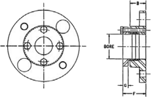
The BY series close coupling is a low cost replacement for gear or elastomeric couplings. It is ideal for use in low to moderate speed applications with motor or turbine drivers. The BY is an economical alternative to Axial Split spacer designs. The BY accommodates close shaft spacings by allowing the connected shafts to extend through the flex discs and spacer without restriction. The spacer is not service removable if the shaft gap is less than the D1 dimension shown. For shorter shaft spacings, the flex discs may still be replaced by removing the coupling bolts and shuttling the spacer from side to side.
| text | ||||
| Coupling Consists of: 2-Hubs-Example-BY43A x 2-1/2” 1-Space Assembly-Example-BY43SAA This coupling is sold as components | Material Classes | Flex Assy Part No. | ||
|---|---|---|---|---|
| Class | Size | |||
| A | 05-25 | AxxSAA | ||
| B | 05-25 | AxxSAB | ||
| C | N/A | N/A | ||
| E | N/A | N/A | ||
| Rated Misalignment: 0.7 Deg/Disc | xx = Size | |||
| Size | Dimensions in Inches | ||||||||||||||
|---|---|---|---|---|---|---|---|---|---|---|---|---|---|---|---|
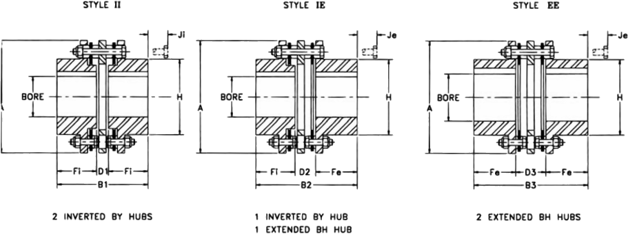
| Max Bore | A | B1 | B2 | B3 | C | DBSE | Fi | Fe | H | Ji | Je | ||||
| BY inv | BH ext | D1 | D2 | D3 | |||||||||||
| 33 | 2.00 | 2.25 | 4.69 | 4.13 | 4.530 | 4.93 | 1.350 | 0.43 | 0.930 | 1.43 | 1.85 | 1.75 | 3.14 | 1.46 | 1.06 |
| 38 | 2.63 | 3.00 | 5.87 | 4.45 | 5.260 | 6.07 | 1.440 | 0.57 | 1.070 | 1.57 | 1.94 | 2.25 | 4.13 | 1.61 | 0.80 |
| 43 | 2.88 | 3.25 | 6.70 | 5.41 | 6.265 | 7.12 | 1.645 | 0.81 | 1.465 | 2.12 | 2.30 | 2.50 | 4.63 | 2.51 | 1.60 |
| 48 | 3.25 | 3.75 | 7.50 | 5.64 | 6.630 | 7.62 | 1.760 | 0.76 | 1.440 | 2.12 | 2.44 | 2.75 | 5.40 | 2.34 | 1.35 |
| 53 | 3.63 | 3.88 | 7.87 | 6.77 | 7.600 | 8.43 | 2.050 | 1.01 | 1.840 | 2.67 | 2.88 | 2.88 | 5.65 | 2.93 | 2.10 |
| 58 | 4.00 | 4.25 | 9.00 | 7.60 | 8.700 | 9.80 | 2.150 | 1.20 | 2.250 | 3.30 | 3.20 | 3.25 | 6.22 | 4.40 | 3.30 |
| 63 | 4.50 | 4.88 | 10.00 | 8.40 | 9.230 | 10.06 | 2.550 | 1.20 | 2.250 | 3.30 | 3.60 | 3.38 | 7.14 | 4.00 | 3.17 |
| 68 | 4.75 | 5.00 | 10.75 | 9.20 | 10.450 | 11.70 | 2.500 | 1.60 | 2.900 | 4.20 | 3.80 | 3.75 | 7.33 | 5.28 | 4.03 |
| Size | HP per 100 RPM | Rated Torque (LB. IN.) | Peak O/L Torque (LB. IN.) | Agma 7 Max RPM | Weight (LBS.) | WR2 (LB. IN.2) | TQ/RAD X106 (LB. IN./RAD) | Free End Float +/- Inch |
|---|---|---|---|---|---|---|---|---|
| 1.0 S.F | ||||||||
| 33 | 4.84 | 3,050 | 4,575 | 8,400 | 8.06 | 22.3 | 0.94 | 0.060 |
| 38 | 10.08 | 6,350 | 9,525 | 7,500 | 13.9 | 65.1 | 2.98 | 0.084 |
| 43 | 19.84 | 12,500 | 18,750 | 6,800 | 23.2 | 144 | 4.99 | 0.090 |
| 48 | 26.98 | 17,000 | 25,500 | 6,500 | 31.1 | 241 | 5.42 | 0.108 |
| 53 | 38.10 | 24,000 | 36,000 | 6,000 | 40.3 | 345 | 9.10 | 0.108 |
| 58 | 53.97 | 34,000 | 51,000 | 5,500 | 65.4 | 734 | 15.4 | 0.118 |
| 63 | 76.19 | 48,000 | 72,000 | 5,200 | 82.8 | 1150 | 25.8 | 0.140 |
| 68 | 114.29 | 72,000 | 108,000 | 4,800 | 106 | 1760 | 37.4 | 0.144 |
| Note: 1) Weight, WR2 and torsional stiffness values shown are for BY hubs at maximum bore size. | ||||||||
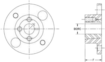
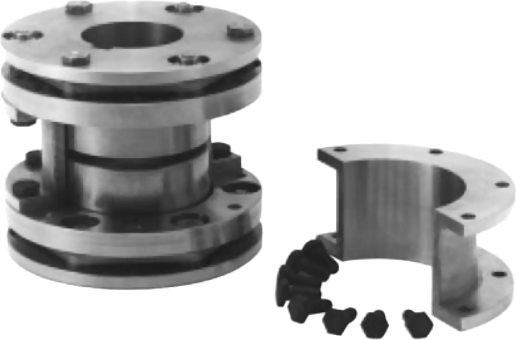
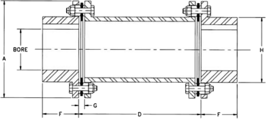
Axial split spacer couplings are an ideal replacement for lubricated gear or grid couplings. Close shaft separations are met without requirements for extending shafts through hubs. The split spacer removes radially to allow removal of connected equipment. Flex discs may be replaced without disturbing the connected equipment. The axial split series features all steel contruction. Stainless steel flex discs are standard for the BA series. Both stainless and high strength alloy steel flex disc options are available with the DA series.
| Ordering: BA and DA Series couplings are sold as components. Please specify hub bore sizes and specify flex disc materials for DA series couplings. | Rated Misalignment: 0.5 Deg/Disc |
| Size | Dimensions in Inches | ||||||
|---|---|---|---|---|---|---|---|
| Max Bore | A | B | D DBSE | F | G | H | |
| BA33 | 1.75 | 4.69 | 3.88 | 0.12 | 1.88 | 0.33 | 2.71 |
| BA38 | 2.50 | 5.87 | 4.38 | 0.12 | 2.13 | 0.40 | 3.55 |
| BA43 | 2.63 | 6.70 | 5.00 | 0.12 | 2.44 | 0.48 | 3.91 |
| DA31 | 3.38 | 7.81 | 5.87 | 0.19 | 2.84 | 0.44 | 5.22 |
| DA35 | 3.75 | 8.69 | 6.81 | 0.25 | 3.28 | 0.54 | 5.71 |
| DA37 | 4.19 | 9.69 | 7.37 | 0.25 | 3.56 | 0.69 | 6.18 |
| DA42 | 4.50 | 10.50 | 8.19 | 0.25 | 3.97 | 0.69 | 6.70 |
| DA45 | 4.75 | 11.31 | 9.31 | 0.31 | 4.50 | 0.75 | 7.20 |
| DA50 | 5.00 | 12.88 | 9.75 | 0.31 | 4.72 | 0.96 | 7.93 |
| DA55 | 5.50 | 14.44 | 11.00 | 0.38 | 5.31 | 1.04 | 8.95 |
| DA60 | 6.00 | 16.00 | 12.38 | 0.38 | 6.00 | 1.10 | 9.89 |
| DA70 | 7.00 | 18.25 | 14.38 | 0.38 | 7.00 | 1.40 | 11.08 |
| Size | HP per 100 RPM | Rated Torque (LB. IN.) | Peak O/L Torque (LB. IN.) | Max RPM | Weight (LBS.) | WR2 (LB. IN.2) | Free End Float +/- Inch | |
|---|---|---|---|---|---|---|---|---|
| 1.0 S.F | Unbalanced | Balanced | ||||||
| BA33 | 6.29 | 3,965 | 7,930 | 4,200 | 7,000 | 10.7 | 29.2 | 0.060 |
| BA38 | 13.10 | 8,255 | 16,510 | 3,800 | 6,300 | 18.1 | 81.7 | 0.084 |
| BA43 | 25.79 | 16,250 | 32,500 | 3,700 | 6,000 | 30.2 | 158 | 0.090 |
| DA31 | 38.10 | 24,000 | 48,000 | 3,000 | 5,000 | 45.5 | 372 | 0.052 |
| DA35 | 54.13 | 34,100 | 68,200 | 2,800 | 4,500 | 63.4 | 627 | 0.056 |
| DA37 | 81.11 | 51,100 | 102,200 | 2,500 | 4,000 | 87 | 1,110 | 0.062 |
| DA42 | 114.76 | 72,300 | 144,600 | 2,300 | 3,700 | 114 | 1,670 | 0.067 |
| DA45 | 130.48 | 82,200 | 164,400 | 2,200 | 3,400 | 152 | 2,550 | 0.072 |
| DA50 | 196.83 | 124,000 | 248,000 | 2,000 | 3,300 | 215 | 4,610 | 0.082 |
| DA55 | 300.00 | 189,000 | 378,000 | 1,900 | 2,800 | 317 | 8,550 | 0.092 |
| DA60 | 390.48 | 246,000 | 492,000 | 1,800 | 2,500 | 450 | 14,900 | 0.102 |
| DA70 | 549.21 | 692,000 | 692,000 | 1,700 | 2,500 | 664 | 28,800 | 0.115 |
| Note: 1) Weight, WR2 and torsional stiffness values shown for BH hubs at maximum bore size. | ||||||||
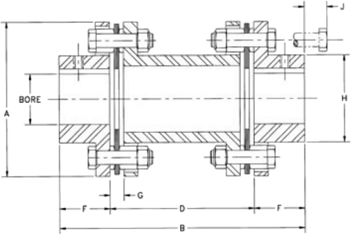
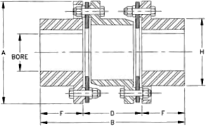
The AK and AP series couplings are standard design spacer couplings. They are made up of two hubs, a one-piece machined spool spacer and two sets of flex discs with standard hardware, including stainless steel flex discs. The AK is the stocked minimum length spacer. The AP is made-to-order to any custom spacer length. AP series pricing is standard for any spacer length up to 9 inches.
| Rated Misalignment: 1.0 Deg/Disc | For type AP, specify the D (DBSE) dimension in 1/100th inches. Example: AP10A350 specifies AP10 class A 3.50” DBSE. | |||||||
| Hub Options | Coupling Consists of: 2-Hubs-Example–AJ25A x 1-3/4” 1-Space Assembly-Example–AK25SAA This coupling is sold as components | Material Classes | Spacer Assembly Part No. | |||||
|---|---|---|---|---|---|---|---|---|
| Hub Type | Size | Class | Size | |||||
| AJ - Standard | 05-45 | A | 05-45 | AKxxSAA | APxxAddd | |||
| AZ Oversize | 05-45 | B | 05-45 | AKxxSAB | APxxBddd | |||
| QD Bushing Mount | 15-40 | C | 15-45 | AKxxSAC | APxxCddd | |||
| AC/AD Clamp | 05-25 | E | MOT 15-45 | AKxxSAE | APxxEddd | |||
| AL Lock Element | 05-25 | xx = Size | ddd = DBSE | |||||
| Size | Dimensions in Inches* | |||||||||
|---|---|---|---|---|---|---|---|---|---|---|
| Max Bore | A | Bmin (AK) | Dmin (AK) | F | G | H | J | Free End Float +/- Inch | ||
| AJ | AZ | |||||||||
| 05 | 0.87 | 1.13 | 2.65 | 3.72 | 1.72 | 1.00 | 0.24 | 1.30 | 0.54 | 0.030 |
| 10 | 1.25 | 1.63 | 3.19 | 4.06 | 2.06 | 1.00 | 0.27 | 1.80 | 0.56 | 0.040 |
| 15 | 1.37 | 1.88 | 3.65 | 4.67 | 2.41 | 1.13 | 0.32 | 2.00 | 0.88 | 0.042 |
| 20 | 1.62 | 2.13 | 4.08 | 5.02 | 2.38 | 1.32 | 0.34 | 2.40 | 0.79 | 0.055 |
| 25 | 2.00 | 2.38 | 4.95 | 6.16 | 2.92 | 1.62 | 0.45 | 2.80 | 1.00 | 0.060 |
| 30 | 2.38 | 2.88 | 5.63 | 7.57 | 3.81 | 1.88 | 0.47 | 3.30 | 1.14 | 0.065 |
| 35 | 2.88 | 3.75 | 6.63 | 8.81 | 4.31 | 2.25 | 0.55 | 4.15 | 0.97 | 0.085 |
| 40 | 3.25 | 4.00 | 7.64 | 9.88 | 4.88 | 2.50 | 0.60 | 4.65 | 1.30 | 0.100 |
| 45 | 3.75 | 4.63 | 8.43 | 11.88 | 5.88 | 3.00 | 0.85 | 5.40 | 0.77 | 0.120 |
| * Dimensions shown are for AJ hubs unless otherwise specified | ||||||||||
| Size | HP per 100 RPM | Rated Torque (LB. IN.) | Peak O/L Torque (LB. IN.) | Agma 7 Max RPM | Weight (LBS.) | WR2 (LB. IN.2) | TQ/RAD X106 (LB. IN./RAD) | |||
|---|---|---|---|---|---|---|---|---|---|---|
| 1.0 S.F | At Min D | Add Per IN. of D | At Min D | Add Per IN. OF D | K Factor | Y Factor | ||||
| 05 | 0.48 | 300 | 600 | 8,500 | 2.32 | 0.14 | 1.87 | 0.05 | 0.15 | 2.00 |
| 10 | 1.27 | 800 | 1,600 | 7,500 | 3.62 | 0.22 | 4.48 | 0.11 | 0.43 | 4.64 |
| 15 | 2.50 | 1,575 | 3,150 | 6,700 | 5.44 | 0.26 | 8.86 | 0.19 | 0.74 | 7.51 |
| 20 | 3.49 | 2,200 | 4,400 | 6,200 | 6.96 | 0.32 | 13.8 | 0.34 | 1.08 | 13.8 |
| 25 | 6.03 | 3,800 | 7,600 | 5,500 | 12.7 | 0.41 | 38.8 | 0.62 | 1.74 | 25.1 |
| 30 | 11.00 | 6,930 | 13,860 | 5,000 | 19.0 | 0.46 | 77.7 | 0.92 | 2.89 | 37.4 |
| 35 | 18.00 | 11,340 | 22,680 | 4,400 | 27.6 | 0.63 | 156 | 2.29 | 5.34 | 93 |
| 40 | 29.00 | 18,270 | 36,540 | 4,000 | 42.1 | 0.76 | 322 | 3.55 | 8.21 | 144 |
| 45 | 48.00 | 30,240 | 60,480 | 3,700 | 55.5 | 1.1 | 507 | 6.77 | 12.5 | 275 |
| Note: | 1) Weight, WR2 and torsional stiffness values shown are for AJ hubs at maximum bore size. 2) To calculate torsional stiffness for a given spacer length, let L=D - Dmin torsional stiffnes = 1/[(1/K) + (L/Y)] | |||||||||
The BP series coupling is a standard design spacer coupling using the 6 bolt disc design. The coupling is made up of two hubs,
a one-piece machined spool spacer and two sets of flex discs with standard hardware, including stainless steel flex discs.
The BP is made-to-order to any custom spacer length. BP series pricing is standard for any spacer length up to 9 inches.
| MEETS API 610 7th EDITION | Rated Misalignment: 0.7 Deg/Disc | ||||||
| Hub Types | Sizes | Coupling Consists of: 2-Hubs-Example-BH33Ax2” 1-Space Assembly-Example-BP33A500 (5”DBSE) This coupling is sold as components | Material Classes | Spacer Assembly Part No. | |||
|---|---|---|---|---|---|---|---|
| BH | 33-78 | Class | Size | ||||
| A | 33-73 | BPxxAddd | |||||
| B | 33-78 | BPxxDbbb | |||||
| Specify the D (DBSE) dimension in 1/100th inches. Example: BP33A350 specifies BP33 class A 3.50” DBSE. Specify each hub bore size as required. | C | 38-63 | BPxCddd | ||||
| E | N/A | N/A | |||||
| ddd = DBSE | |||||||
| Size | Dimensions in Inches | ||||||
|---|---|---|---|---|---|---|---|
| Max Bore | A | Dmin | F | G | H | Free End Float +/- Inch | |
| 33 | 2.25 | 4.69 | 2.09 | 1.75 | 0.285 | 3.14 | 0.060 |
| 38 | 3.00 | 5.87 | 2.37 | 2.25 | 0.335 | 4.13 | 0.084 |
| 43 | 3.25 | 6.70 | 2.95 | 2.50 | 0.465 | 4.63 | 0.090 |
| 48 | 3.75 | 7.50 | 3.00 | 2.75 | 0.495 | 5.40 | 0.108 |
| 53 | 3.88 | 7.87 | 3.91 | 2.88 | 0.520 | 5.65 | 0.108 |
| 58 | 4.25 | 9.00 | 4.80 | 3.25 | 0.555 | 6.22 | 0.118 |
| 63 | 4.88 | 10.00 | 4.88 | 3.38 | 0.600 | 7.14 | 0.140 |
| 68 | 5.00 | 10.75 | 6.20 | 3.75 | 0.849 | 7.33 | 0.144 |
| 73 | 5.25 | 12.50 | 7.70 | 5.13 | 1.000 | 7.80 | 0.156 |
| 78 | 6.50 | 14.90 | 8.08 | 6.38 | 0.940 | 9.50 | 0.165 |
| Size | HP per 100 RPM | Rated Torque (LB. IN.) | Peak O/L Torque (LB. IN.) | Agma 8 Max RPM | Weight (LBS.) | WR2 (LB. IN.2) | TQ/RAD X106 (LB. IN./RAD) | |||
|---|---|---|---|---|---|---|---|---|---|---|
| 1.0 S.F | At Min D | Add Per IN. of D | At Min D | Add Per IN. of D | K Factor | Y Factor | ||||
| 33 | 4.84 | 3,050 | 6,100 | 8,400 | 8.49 | 0.47 | 23.3 | 0.91 | 2.42 | 37.1 |
| 38 | 10.08 | 6,350 | 12,700 | 7,500 | 15.9 | 0.63 | 71.8 | 2.24 | 4.93 | 90.8 |
| 43 | 19.84 | 12,500 | 25,000 | 6,800 | 24.3 | 0.74 | 143 | 3.59 | 9.40 | 146 |
| 48 | 26.98 | 17,000 | 34,000 | 6,500 | 33.2 | 0.87 | 248 | 5.79 | 13.2 | 235 |
| 53 | 38.10 | 24,000 | 48,000 | 6,000 | 41.7 | 0.93 | 354 | 6.93 | 15.1 | 281 |
| 58 | 53.97 | 34,000 | 68,000 | 5,500 | 65.1 | 0.98 | 707 | 8.14 | 23.7 | 330 |
| 63 | 76.19 | 48,000 | 96,000 | 5,200 | 80.5 | 1.14 | 1,100 | 13.0 | 34.9 | 528 |
| 68 | 114.29 | 72,000 | 144,000 | 4,800 | 104 | 1.17 | 1,560 | 14.7 | 44.0 | 597 |
| 73 | 198.41 | 125,000 | 250,000 | 4,200 | 174 | 2.17 | 3,500 | 33.2 | 71.2 | 1,350 |
| 78 | 369.84 | 233,000 | 466,000 | 3,700 | 302 | 3.28 | 8,540 | 68.0 | 131 | 2,760 |
| Note: | 1) Weight, WR2 and torsional stiffness values shown are for BH hubs at maximum bore size. 2) To calculate torsional stiffness for a given spacer length, let L=D - Dmin torsional stiffnes = 1/[(1/K) + (L/Y)] | |||||||||
The DP series coupling is a fully machined spacer coupling using the 8 bolt disc design used for high torque applications at higher speeds. The coupling is made up of two hubs, a one-piece machined spool spacer and two sets of flex discs and hardware. The DP is made-to-order to any customer spacer length.Both stainless and high strength alloy flex disc materials are available.
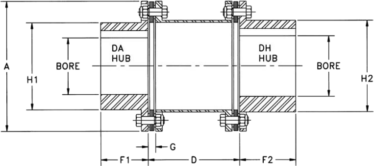
| MEETS API 610 7th EDITION | Rated Misalignment: 0.5 Deg/Disc | ||
| Specify Bores & DBSE This coupling is sold as an assembly. | |||
| Size | Dimensions in Inches | |||||||||
|---|---|---|---|---|---|---|---|---|---|---|
| Max Bore | A | Dmin DBSE | F1 DA | F2 DH | G | H1 DA | H2 DH | Free End Float +/- Inch | ||
| DA | DH | |||||||||
| DP31 | 3.38 | 3.63 | 7.81 | 4.38 | 2.84 | 3.37 | 0.44 | 5.22 | 5.50 | 0.052 |
| DP35 | 3.75 | 4.00 | 8.69 | 4.75 | 3.28 | 3.75 | 0.54 | 5.71 | 5.88 | 0.056 |
| DP37 | 4.00 | 4.50 | 9.69 | 5.00 | 3.56 | 4.00 | 0.69 | 6.18 | 6.50 | 0.062 |
| DP42 | 4.50 | 4.75 | 10.50 | 5.13 | 3.97 | 4.25 | 0.69 | 6.70 | 7.00 | 0.067 |
| DP45 | 4.75 | 5.13 | 11.31 | 5.25 | 4.50 | 4.50 | 0.75 | 7.20 | 7.44 | 0.072 |
| DP50 | 5.00 | 5.38 | 12.88 | 7.25 | 4.72 | 5.00 | 0.96 | 7.93 | 8.38 | 0.082 |
| DP55 | 5.50 | 6.00 | 14.44 | 7.62 | 5.31 | 5.50 | 1.04 | 8.95 | 9.44 | 0.092 |
| DP60 | 6.00 | 6.50 | 16.00 | 8.13 | 6.00 | 6.00 | 1.10 | 9.89 | 10.25 | 0.102 |
| DP70 | 7.00 | 7.50 | 18.25 | 9.25 | 7.00 | 7.00 | 1.40 | 11.06 | 11.75 | 0.115 |
| Size | HP per 100 RPM | Rated Torque (LB. IN.) | Peak O/L Torque (LB. IN.) | Agma 8 Max RPM | Weight (LBS.) | WR2 (LB. IN.2) | TQ/RAD X106 (LB. IN./RAD) | |||
|---|---|---|---|---|---|---|---|---|---|---|
| 1.0 S.F | At Min D | Add Per IN. of D | At Min D | Add Per IN. of D | K Factor | Y Factor | ||||
| DP31 | 38.10 | 24,000 | 48,000 | 6,500 | 37.2 | 0.60 | 289 | 4.30 | 16.7 | 168 |
| DP35 | 69.84 | 44,000 | 88,000 | 5,700 | 54.5 | 0.97 | 525 | 8.16 | 26.7 | 318 |
| DP37 | 95.24 | 60,000 | 120,000 | 5,400 | 69.3 | 1.05 | 839 | 10.7 | 34.7 | 417 |
| DP42 | 115.87 | 73,000 | 146,000 | 5,100 | 91.4 | 1.54 | 1,270 | 18.2 | 47.2 | 711 |
| DP45 | 136.98 | 86,300 | 172,600 | 4,800 | 118 | 1.66 | 1,910 | 23.4 | 61.0 | 912 |
| DP50 | 203.17 | 128,000 | 256,000 | 4,300 | 175 | 2.28 | 3,560 | 38.3 | 78.7 | 1,490 |
| DP55 | 300.00 | 189,000 | 378,000 | 4,100 | 260 | 3.03 | 6,690 | 63.2 | 133 | 2,470 |
| DP60 | 414.29 | 261,000 | 522,000 | 3,600 | 367 | 4.01 | 11,600 | 101 | 187 | 3,950 |
| DP70 | 658.73 | 415,000 | 830,000 | 3,300 | 559 | 5.46 | 23,500 | 172 | 285 | 6,690 |
| Note: | 1) Weight, WR2 and torsional stiffness values shown are for DA hubs at maximum bore size. 2) To calculate torsional stiffness for a given spacer length, let L=D - Dmin torsional stiffnes = 1/[(1/K) + (L/Y)] | |||||||||
The BF series is designed for moderate service in higher speed application. The coupling consists of factory assembled spacer unit which mounts between two hubs. The spacer assembly drops out as one unit for easy maintenance. The BF has all steel construction with standard stainless steel flex discs. The coupling is manufactured to meet AGMA class 9 balance requirements. Dynamic balancing for higher speed operation is alos available. Standard length spacers are stocked. Pricing is standard for any spacer length up to the Dmax value listed. Longer spacer lengths are also available. Models BF15 and BF20 use a 4 bolt disc design.
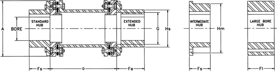
| Specify Bores & DBSE This coupling is sold as components unless balanced. | MEETS API 610 7th EDITION | MEETS API 610 8th EDITION WHEN FURNISHED BALANCED |
| Size | Dimensions in Inches | ||||||||||||
|---|---|---|---|---|---|---|---|---|---|---|---|---|---|
| Max Bore | A | DBSE | Fs Std Interm, | Fe Ext | Fl Lrg | G Max | Hs Std | Hm Interm. | |||||
| Std Ext | Interm. Hub | Large Hub | Dmin | Dmax* | Stock | ||||||||
| 15(3) | 1.50 | 1.88 | 2.38 | 3.65 | 3.43 | 9.00 | 3.5, 4.37 | 1.31 | 1.69 | 1.63 | 2.09 | 2.33 | 2.75 |
| 20(3) | 1.88 | 2.13 | 2.75 | 4.19 | 3.43 | 9.00 | 3.5, 4.37, 5 | 1.56 | 2.06 | 1.81 | 2.56 | 2.81 | 3.00 |
| 33 | 2.25 | - | 3.25 | 4.93 | 3.09 | 9.00 | 3.5, 5, 7 | 2.00 | 2.50 | 2.06 | 3.13 | 3.38 | - |
| 38 | 3.00 | - | 4.00 | 6.00 | 3.50 | 9.00 | 5, 7 | 2.63 | 3.25 | 2.75 | 4.13 | 4.43 | - |
| 43 | 3.50 | - | 4.50 | 6.77 | 4.43 | 9.00 | 5, 7 | 3.12 | 3.75 | 3.00 | 5.00 | 5.25 | - |
| 48 | 3.75 | - | 5.00 | 7.62 | 4.50 | 9.00 | 5, 7 | 3.25 | 4.00 | 3.25 | 5.38 | 5.63 | - |
| 53 | 4.13 | - | - | 8.00 | 5.69 | 9.00 | 7 | 3.63 | 4.38 | - | 5.75 | 6.13 | - |
| 58 | 4.63 | - | - | 9.00 | 6.88 | 9.00 | 7 | 4.12 | 5.00 | - | 6.50 | 6.88 | - |
| 63 | 5.13 | - | - | 10.00 | 6.93 | 9.00 | 7 | 4.50 | 5.38 | - | 7.25 | 7.63 | - |
| 68 | 5.63 | - | - | 11.00 | 7.56 | 12.00 | - | 5.00 | 6.00 | - | 8.00 | 8.38 | - |
| 73 | 6.50 | - | - | 12.75 | 11.00 | 12.00 | - | 5.13 | 6.38 | - | 8.38 | 9.38 | - |
| 78 | 7.50 | - | - | 15.30 | 11.88 | 12.00 | - | 6.38 | 7.38 | - | 10.19 | 10.75 | - |
| Size | HP per 100 RPM | Rated Torque (LB. IN.) | Peak O/L Torque (LB. IN.) | Max RPM | Weight (LBS.) | WR2 (LB. IN.2) | TQ/RAD X106 (LB. IN./RAD) | FREE END FLOAT +/- INCH | ||||
|---|---|---|---|---|---|---|---|---|---|---|---|---|
| 1.0 S.F | Agma 9 | Balance D | At Min D | Add Per IN. of D | At Min D | Add Per IN. of D | K Factor | Y Factor | ||||
| (3)15 | 2.50 | 1,575 | 3,150 | 13,500 | 23,500 | 7.38 | 0.12 | 11.75 | 0.05 | 0.46 | 2.09 | 0.045 |
| (3)20 | 3.49 | 2,200 | 4,400 | 12,500 | 20,000 | 10.1 | 0.19 | 23.0 | 0.15 | 0.87 | 3.72 | 0.055 |
| 33 | 4.84 | 3,050 | 6,100 | 11,000 | 27,400 | 14.8 | 0.47 | 43.3 | 0.91 | 2.49 | 37.1 | 0.060 |
| 38 | 10.89 | 6,860 | 13,720 | 9,800 | 14,300 | 28.1 | 0.63 | 129 | 2.24 | 5.04 | 90.8 | 0.084 |
| 43 | 21.43 | 13,500 | 27,000 | 8,800 | 12,700 | 44.5 | 0.70 | 276 | 3.05 | 9.66 | 124 | 0.090 |
| 48 | 29.21 | 18,400 | 36,800 | 8,300 | 11,000 | 54.3 | 0.79 | 422 | 4.61 | 12.8 | 187 | 0.108 |
| 53 | 38.10 | 24,000 | 48,000 | 7,800 | 10,700 | 72 | 0.88 | 633 | 5.92 | 14.9 | 240 | 0.108 |
| 58 | 65.08 | 41,000 | 82,000 | 7,000 | 9,475 | 107 | 0.98 | 1,200 | 8.14 | 23.4 | 330 | 0.118 |
| 63 | 76.19 | 48,000 | 96,000 | 6,700 | 8,590 | 134 | 1.14 | 1,870 | 13.0 | 33.5 | 528 | 0.140 |
| 68 | 114.29 | 72,000 | 144,000 | 6,200 | 7,800 | 188 | 1.48 | 3,020 | 16.2 | 44.7 | 569 | 0.144 |
| 73 | 198.41 | 125,000 | 250,000 | 5,700 | 6,740 | 272 | 2.02 | 5,990 | 27.0 | 75.1 | 1,100 | 0.156 |
| 78 | 369.84 | 233,000 | 466,000 | 5,000 | 5,600 | 475 | 3.21 | 14,700 | 63.8 | 142 | 2,590 | 0.170 |
| Note: | 1) Weight, WR2 and torsional stiffness values shown are for standard hubs at maximum bore size. 2) To calculate torsional stiffness for a given spacer length, let L=D - Dmin torsional stiffness = 1/[)1/K) + (L/Y)] 3) 4 bolt disc design | |||||||||||
The HSH series is designed for high torque, low speed applications. Hubs and spacers are cast of iron or steel. Flex discs are high strength alloy steel. Stainless steel flex discs are optional. Dynamic balancing for higher speed operation is not recommended. Single plane balancing of hubs and spacers is available.
Rated Misalignment: 0.3 Deg/Disc
| Hub Types | Sizes |
|---|---|
| C.I. | 22-160 |
| STL | 31-160 |
| Ordering: HSH Series couplings are sold as complete assemblies. Please specify hub type, bore sizes and flex disc materials. A coupling will be configured to meet your specification. | |
| Size | Dimensions in Inches | |||||||
|---|---|---|---|---|---|---|---|---|
| Max Bore | A | B | D DBSE | F | G | H | ||
| Iron | Steel | |||||||
| 22 | 2.25 | - | 6.00 | 8.00 | 3.00 | 2.50 | 0.43 | 3.87 |
| 26 | 2.62 | - | 6.87 | 9.50 | 3.50 | 2.88 | 0.55 | 4.50 |
| 31 | 3.12 | 3.25 | 8.12 | 10.87 | 4.12 | 3.38 | 0.62 | 5.50 |
| 35 | 3.62 | 3.81 | 9.12 | 12.06 | 4.56 | 3.75 | 0.66 | 6.12 |
| 37 | 3.75 | 4.19 | 10.06 | 13.12 | 5.12 | 4.00 | 0.81 | 6.50 |
| 42 | 4.25 | 4.50 | 11.00 | 13.93 | 5.43 | 4.25 | 0.81 | 7.00 |
| 45 | 4.50 | 4.75 | 11.87 | 14.75 | 5.75 | 4.50 | 0.87 | 7.43 |
| 50 | 5.12 | 5.50 | 13.43 | 16.81 | 6.81 | 5.00 | 1.06 | 9.50 |
| 55 | 5.62 | 6.25 | 15.00 | 18.68 | 7.68 | 5.50 | 1.25 | 9.50 |
| 60 | 6.50 | 7.12 | 16.75 | 20.93 | 8.43 | 6.25 | 1.34 | 10.50 |
| 70 | 7.00 | 7.87 | 18.93 | 23.62 | 9.62 | 7.00 | 1.50 | 11.75 |
| 75 | 7.75 | 8.75 | 20.62 | 25.00 | 10.50 | 7.25 | 1.53 | 13.00 |
| 80 | 8.00 | 9.12 | 22.37 | 26.87 | 11.37 | 7.75 | 1.56 | 13.75 |
| 85 | 8.50 | 9.62 | 23.75 | 28.62 | 12.12 | 8.25 | 1.62 | 14.50 |
| 92 | 10.00 | 11.00 | 25.75 | 31.00 | 13.00 | 9.00 | 1.75 | 15.87 |
| 105 | 10.50 | 12.00 | 29.25 | 34.25 | 13.25 | 10.50 | 1.75 | 20.00 |
| 160 | 16.00 | 17.00 | 33.50 | 30.25 | 16.25 | 12.00 | 2.25 | 24.00 |
| Size | HP per 100 RPM | Rated Torque (LB. IN.) | Peak O/L Torque (LB. IN.) | Max RPM | Weight (LBS.) | WR2 (LB. IN.2) | TQ/RAD X106 (LB. IN./RAD) | FREE END FLOAT +/- INCH |
|---|---|---|---|---|---|---|---|---|
| 1.0 S.F | ||||||||
| 22 | 15.08 | 9,500 | 14,250 | 3,800 | 22 | 80 | 1.5 | 0.036 |
| 26 | 25.40 | 16,000 | 24,000 | 3,300 | 33 | 161 | 2.3 | 0.044 |
| 31 | 38.10 | 24,000 | 36,000 | 2,800 | 56 | 401 | 2.9 | 0.052 |
| 35 | 69.84 | 44,000 | 66,000 | 2,600 | 81 | 750 | 6.5 | 0.056 |
| 37 | 95.24 | 60,000 | 90,000 | 2,500 | 103 | 1,130 | 9.9 | 0.062 |
| 42 | 115.87 | 73,000 | 109,500 | 2,400 | 133 | 1,740 | 6.9 | 0.067 |
| 45 | 157.14 | 99,000 | 148,500 | 2,250 | 161 | 2,510 | 14.8 | 0.072 |
| 50 | 203.17 | 128,000 | 192,000 | 2,000 | 223 | 4,580 | 44.3 | 0.082 |
| 55 | 300.00 | 189,000 | 283,500 | 1,800 | 302 | 7,480 | 54.2 | 0.092 |
| 60 | 414.29 | 261,000 | 391,500 | 1,600 | 435 | 13,800 | 80.1 | 0.102 |
| 70 | 658.73 | 415,000 | 622,500 | 1,400 | 640 | 25,900 | 144 | 0.115 |
| 75 | 846.03 | 533,000 | 799,500 | 1,300 | 839 | 38,600 | 148 | 0.125 |
| 80 | 1,087.30 | 685,000 | 1,027,500 | 1,200 | 1,070 | 59,800 | 205 | 0.136 |
| 85 | 1,315.87 | 829,000 | 1,243,500 | 1,100 | 1,240 | 79,400 | 204 | 0.140 |
| 92 | 1,650.79 | 1,040,000 | 1,560,000 | 1,000 | 1,710 | 131,000 | 384 | 0.156 |
| 105 | 1,984.13 | 1,250,000 | 1,875,000 | 1,000 | c/f | c/f | c/f | 0.170 |
| 160 | 3,174.60 | 2,000,000 | 3,000,000 | 900 | c/f | c/f | c/f | 0.250 |
| Note: | 1) Weight, WR2 and torsional stiffness values shown are for Cast Iron hubs at maximum bore size. | |||||||
The FSH series is designed for high torque, low speed applications. Hubs and spacers are cast of iron or steel. Adapter plates are cast grey or ductile iron. Flex discs are high strength alloy steel. Stainless flex discs are optional. Dynamic balancing for higher speed operation is not recommended. Single plane balancing of flywheel adapters, hubs and spacers is available.
| Hub Types | Sizes | Ordering: HSH Series couplings are sold as complete assemblies. Please specify hub type, bore sizes. and flex disc materials. A coupling will be configured to meet your specification. | 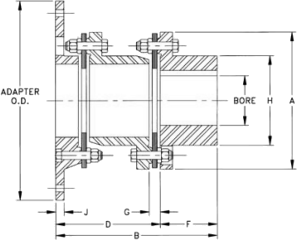 | |||||
|---|---|---|---|---|---|---|---|---|
| C.I. | 31-105 | |||||||
| STL | 31-105 | |||||||
| STANDARD ADAPTER SIZES | ||||||||
| Size | OD | SAE Bolting | HD Bolting | |||||
| BC | Hole Qty | Hole Size | BC | Hole Qty | Hole Size | |||
| 10 | 10.375 | 9.625 | 6 | 13/32 | 9,500 | 8 | 15/32 | |
| 12 | 12.375 | 11.625 | 8 | 13/32 | 11,500 | 8 | 17/32 | |
| 14 | 13.875 | 13.125 | 8 | 13/32 | 12,500 | 8 | 21/32 | |
| 18 | 18.375 | 17.250 | 8 | 17/32 | 16,750 | 8 | 25/32 | |
| 20 | 20.375 | 19.250 | 8 | 17/32 | 18,500 | 8 | 29/32 | |
| 22 | 22.500 | 21.375 | 6 | 21/32 | 20,500 | 8 | 1-1/32 | |
| 26 | 26.500 | 25.250 | 12 | 21/32 | 24,500 | 12 | 1-1/32 | |
| 28 | 28.875 | 27.250 | 12 | 25/32 | 26,875 | 12 | 1-1/32 | Rated Misalignment: 0.3 Deg/Disc |
| Size | Dimensions in Inches | AVAILABLE ADAPTER SIZES MAX BORE X = STOCK SIZE 0 = MTO | |||||||||||||||
|---|---|---|---|---|---|---|---|---|---|---|---|---|---|---|---|---|---|
| Max Bore | A | B | D DBSE | F | G | H | J | ||||||||||
| Iron | Steel | 10 | 12 | 14 | 18 | 20 | 22 | 26 | 28 | ||||||||
| 31 | 3.12 | 3.25 | 8.12 | 8.68 | 5.31 | 3.37 | 0.62 | 5.50 | 0.50 | O | O | X | X | O | O | ||
| 35 | 3.62 | 3.81 | 9.12 | 9.62 | 5.87 | 3.75 | 0.66 | 6.12 | 0.50 | O | O | X | X | O | X | ||
| 37 | 3.75 | 4.19 | 10.06 | 10.62 | 6.62 | 4.00 | 0.81 | 6.50 | 0.56 | O | O | O | O | ||||
| 42 | 4.25 | 4.50 | 11.00 | 11.37 | 7.12 | 4.25 | 0.81 | 7.00 | 0.63 | O | X | O | X | X | X | ||
| 45 | 4.50 | 4.75 | 11.87 | 12.00 | 7.50 | 4.50 | 0.87 | 7.43 | 0.69 | O | X | O | X | X | X | ||
| 50 | 5.12 | 5.50 | 13.43 | 13.75 | 8.75 | 5.00 | 1.06 | 8.37 | 0.75 | X | O | X | X | X | |||
| 55 | 5.62 | 6.25 | 15.00 | 15.38 | 9.87 | 5.50 | 1.25 | 9.50 | 0.88 | X | O | X | X | X | |||
| 60 | 6.50 | 7.12 | 16.75 | 17.12 | 10.87 | 6.25 | 1.34 | 10.50 | 1.00 | X | O | X | X | X | |||
| 70 | 7.00 | 7.87 | 18.93 | 19.43 | 12.43 | 7.00 | 1.50 | 11.75 | 1.00 | X | X | X | |||||
| 75 | 7.75 | 8.75 | 20.62 | 20.75 | 13.50 | 7.25 | 1.53 | 13.00 | 1.13 | O | O | X | |||||
| 80 | 8.00 | 9.12 | 22.37 | 22.50 | 14.75 | 7.75 | 1.56 | 13.75 | 1.25 | O | O | X | |||||
| 85 | 8.50 | 9.62 | 23.75 | 23.93 | 15.68 | 8.25 | 1.62 | 14.50 | 1.25 | X | |||||||
| 92 | 10.00 | 11.00 | 25.75 | 26.25 | 17.25 | 9.00 | 1.75 | 15.87 | 1.38 | X | |||||||
| 105 | 10.50 | 12.00 | 29.25 | 27.77 | 17.27 | 10.50 | 1.75 | 20.00 | 1.75 | ||||||||
| Size | HP per 100 RPM | Rated Torque (LB. IN.) | Peak O/L Torque (LB. IN.) | Max RPM (2) | Weight (LBS.) (1) | WR2 (LB. IN.2) (1) | TQ/RAD X106 (LB. IN./RAD) | FREE END FLOAT +/- INCH |
|---|---|---|---|---|---|---|---|---|
| 1.0 S.F | ||||||||
| 31 | 38.10 | 24,000 | 36,000 | 2,800 | 48 | 442 | 2.95 | 0.052 |
| 35 | 69.84 | 44,000 | 66,000 | 2,600 | 64 | 661 | 6.69 | 0.056 |
| 37 | 95.24 | 60,000 | 90,000 | 2,500 | 87 | 1,170 | 10.3 | 0.062 |
| 42 | 115.9 | 73,000 | 109,500 | 2,400 | 115 | 1,860 | 7.03 | 0.067 |
| 45 | 157.1 | 99,000 | 148,500 | 2,250 | 138 | 2,500 | 15.4 | 0.072 |
| 50 | 203.2 | 128,000 | 192,000 | 2,000 | 202 | 5,550 | 48.8 | 0.082 |
| 55 | 300.0 | 189,000 | 283,500 | 1,800 | 263 | 8,000 | 58.6 | 0.092 |
| 60 | 414.3 | 261,000 | 391,500 | 1,600 | 359 | 12,700 | 86.5 | 0.102 |
| 70 | 658.7 | 415,000 | 622,500 | 1,400 | 559 | 26,200 | 161 | 0.115 |
| 75 | 846.0 | 533,000 | 799,500 | 1,300 | 766 | 43,600 | 160 | 0.125 |
| 80 | 1087 | 685,000 | 1,027,500 | 1,200 | 930 | 60,100 | 225 | 0.136 |
| 85 | 1316 | 829,000 | 1,243,500 | 1,100 | 1,110 | 83,000 | 222 | 0.140 |
| 92 | 1651 | 1,040,000 | 1,560,000 | 1,000 | 1,460 | 124,000 | 433 | 0.156 |
| 105 | 1984 | 1,250,000 | 1,875,000 | 1,000 | c/f | c/f | c/f | 0.170 |
| Note: | 1) Weight, WR2 and torsional stiffness values shown are for Cast Iron hubs at maximum bore size and minimum available adapter O.D. 2) Max RPM listed is for smallest adapter size. Consult factory for speed ratings by adapter size. | |||||||
The A5 series is used for spacer lengths that are longer than can be spanned economically with spacer couplings. The A5 series has a welded tubular spacer assembly along with two hubs and standard hardware, including stainless steel flex discs. The A5 is made-to-order to any customer spacer length. A5 series standard pricing is listed for D dimensions up to 36 inches and for D dimensions from 36 inches to maximum D at 1800 RPM.
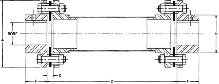
| Rated Misalignment: 1.0 Deg/Disc | ||||||
| Hub Options | Ordering: A5 Series couplings are sold as complete assemblies. Please specify hub types and bore sizes, DBSE (D) dimension, speed for dynamic balancing, and material class. A coupling will be configured to meet your specifications. Ordering type A6 for vertical applications longer than 30” DBSE. A thrust button will be added on the lower end of the spacer to support the weight of the spacer. | Material Classes | ||||
|---|---|---|---|---|---|---|
| Hub Type | Size | Class | Size | |||
| AJ - Standard | 05-45 | A | 05-45 | |||
| AZ Oversize | 05-45 | B | 05-45 | |||
| QD Bushing Mount | 15-40 | C | 15-45 | |||
| AC/AD Clamp | 05-25 | E | 15-45 | |||
| AL Lock Element | 05-25 | |||||
| Size | Dimensions in Inches* | Max DBSE (D Inches) for RPM Shown | |||||||||||
|---|---|---|---|---|---|---|---|---|---|---|---|---|---|
| Max Bore | A | Dmin | F | G | H | ||||||||
| Aj | Az | 1800 | 1500 | 1200 | 900 | 750 | 600 | ||||||
| 05 | 0.87 | 1.13 | 2.65 | 4.00 | 1.00 | 0.24 | 1.30 | 51 | 56 | 62 | 71 | 78 | 87 |
| 10 | 1.25 | 1.63 | 3.19 | 4.00 | 1.00 | 0.27 | 1.80 | 62 | 69 | 76 | 88 | 96 | 107 |
| 15 | 1.37 | 1.88 | 3.65 | 5.00 | 1.13 | 0.32 | 2.00 | 64 | 71 | 79 | 91 | 99 | 111 |
| 20 | 1.62 | 2.13 | 4.08 | 5.00 | 1.32 | 0.34 | 2.40 | 73 | 81 | 90 | 103 | 113 | 126 |
| 25 | 2.00 | 2.38 | 4.95 | 5.00 | 1.62 | 0.45 | 2.80 | 79 | 87 | 97 | 112 | 122 | 137 |
| 30 | 2.38 | 2.88 | 5.63 | 6.00 | 1.88 | 0.47 | 3.30 | 85 | 94 | 102 | 120 | 132 | 147 |
| 35 | 2.88 | 3.75 | 6.63 | 7.00 | 2.25 | 0.55 | 4.15 | 97 | 107 | 119 | 137 | 150 | 168 |
| 40 | 3.25 | 4.00 | 7.64 | 7.00 | 2.50 | 0.60 | 4.65 | 103 | 113 | 126 | 146 | 160 | 178 |
| 45 | 3.75 | 4.63 | 8.43 | 8.00 | 3.00 | 0.85 | 5.40 | 113 | 125 | 139 | 160 | 175 | 196 |
| * Dimensions shown are for AJ hubs unless otherwise specified | |||||||||||||
| Size | HP per 100 RPM | Rated Torque (LB. IN.) | Peak O/L Torque (LB. IN.) | Weight (LBS.) | WR2 (LB. IN.2) | Tors. Stiffness 106 (LB. IN./RAD) | FREE END FLOAT +/- INCH | |||
|---|---|---|---|---|---|---|---|---|---|---|
| 1.0 S.F | At D = 20” | Add Per IN. of D | At D = 20” | Add Per IN. of D | K Factor | Y Factor | ||||
| 05 | 0.48 | 300 | 600 | 4.37 | 0.11 | 2.38 | 0.03 | 0.04 | 1.12 | 0.030 |
| 10 | 1.27 | 800 | 1,600 | 5.64 | 0.10 | 5.88 | 0.07 | 0.11 | 2.81 | 0.040 |
| 15 | 2.50 | 1,575 | 3,150 | 7.48 | 0.10 | 10.3 | 0.07 | 0.13 | 2.81 | 0.042 |
| 20 | 3.49 | 2,200 | 4,400 | 11.5 | 0.21 | 18.3 | 0.22 | 0.35 | 8.77 | 0.055 |
| 25 | 6.03 | 3,800 | 7,600 | 17.0 | 0.20 | 45.0 | 0.29 | 0.52 | 12.0 | 0.060 |
| 30 | 11.00 | 6,930 | 13,860 | 25.7 | 0.29 | 90.6 | 0.56 | 0.98 | 22.7 | 0.065 |
| 35 | 18.00 | 11,340 | 22,680 | 34.8 | 0.40 | 180 | 1.32 | 1.99 | 53.9 | 0.085 |
| 40 | 29.00 | 18,270 | 36,540 | 49.9 | 0.46 | 356 | 1.95 | 3.14 | 79.3 | 0.100 |
| 45 | 48.00 | 30,240 | 60,480 | 75.7 | 0.54 | 614 | 3.22 | 5.57 | 131 | 0.120 |
| Note: | 1) Weight, WR2 and torsional stiffness values shown are for AJ hubs at maximum bore size. 2) To calculate torsional stiffness for a given spacer length, let L=D - Dmin torsional stiffness = 1/[(1/K) + (L/Y)] | |||||||||
The A7 coupling is a single flexing coupling designed for use in widely spaced three bearing systems. The shaft end of the coupling must be supported by a self-aligning bearing. A full floating coupling may be used in combination with the semi-floating coupling to span longer distances, or a V-belt drive or other component may be mounted to the shaft end. This A7 is made-to-order to any custom spacer length. A7 series standard pricing is listed at D dimensions up to 36 inches and D dimensions between 36 inches and max L at 1800 RPM motor speed.
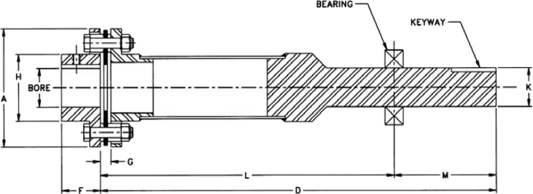
| Rated Misalignment: 1.0 Deg/Disc | ||||||
| Hub Options | Ordering: A5 Series couplings are sold as complete assemblies. Please specify hub types and bore sizes, DBSE (D) dimension, speed for dynamic balancing, and material class. A coupling will be configured to meet your specifications. | Material Classes | ||||
|---|---|---|---|---|---|---|
| Hub Type | Size | Class | Size | |||
| AJ - Standard | 05-45 | A | 10-45 | |||
| AZ Oversize | 05-45 | B | 05-45 | |||
| QD Bushing Mount | 15-40 | C | 15-45 | |||
| AC/AD Clamp | 05-25 | E | 15-45 | |||
| AL Lock Element | 05-25 | |||||
| Size | Dimensions in Inches* | Max DBSE (D Inches) for RPM Shown | ||||||||||||||
|---|---|---|---|---|---|---|---|---|---|---|---|---|---|---|---|---|
| Max Bore | A | Dmin | F | G | H | K | L | M | Keyway Size | |||||||
| Aj | Az | 1800 | 1500 | 1200 | 900 | 600 | ||||||||||
| 10 | 1.25 | 1.63 | 3.19 | 20 | 1.00 | 0.27 | 1.80 | 1.25 | 16.50 | 3.50 | .25 x .12 | 62 | 69 | 76 | 88 | 107 |
| 15 | 1.37 | 1.88 | 3.65 | 20 | 1.13 | 0.32 | 2.00 | 1.25 | 16.06 | 3.94 | .25 x .12 | 64 | 71 | 79 | 91 | 111 |
| 20 | 1.62 | 2.13 | 4.08 | 20 | 1.32 | 0.34 | 2.40 | 1.50 | 15.75 | 4.25 | .37 x .18 | 73 | 81 | 90 | 103 | 126 |
| 25 | 2.00 | 2.38 | 4.95 | 20 | 1.62 | 0.45 | 2.80 | 1.75 | 15.25 | 4.75 | .37 x .18 | 79 | 87 | 97 | 112 | 137 |
| 30 | 2.38 | 2.88 | 5.63 | 20 | 1.88 | 0.47 | 3.30 | 2.00 | 14.50 | 5.50 | .50 x .25 | 85 | 94 | 102 | 120 | 147 |
| 35 | 2.88 | 3.75 | 6.63 | 20 | 2.25 | 0.55 | 4.15 | 2.50 | 13.25 | 6.75 | .62 x .31 | 97 | 107 | 119 | 137 | 168 |
| 40 | 3.25 | 4.00 | 7.64 | 20 | 2.50 | 0.60 | 4.65 | 3.00 | 12.75 | 7.25 | .75 x .37 | 103 | 113 | 126 | 146 | 178 |
| 45 | 3.75 | 4.63 | 8.43 | 20 | 3.00 | 0.85 | 5.40 | 3.44 | 12.75 | 7.25 | .87 x .43 | 113 | 125 | 139 | 160 | 196 |
| * Dimensions shown are for AJ hubs unless otherwise specified | ||||||||||||||||
| Size | HP per 100 RPM | Rated Torque (LB. IN.) | Peak O/L Torque (LB. IN.) | Max Radial Load - (LBS) | Weight (LBS.) | WR2 (LB. IN.2) | Tors. Stiffness 106 (LB. IN./RAD) | Free End Float +/- Inch | |||
|---|---|---|---|---|---|---|---|---|---|---|---|
| 1.0 S.F | At D = 20” | Add Per IN. of D | At D = 20” | Add Per IN. of D | K Factor | Y Factor | |||||
| 10 | 1.27 | 800 | 1,600 | 34 | 5.37 | 0.10 | 3.30 | 0.07 | 0.26 | 2.81 | 0.020 |
| 15 | 2.50 | 1,575 | 3,150 | 56 | 6.65 | 0.10 | 5.72 | 0.07 | 0.28 | 2.81 | 0.021 |
| 20 | 3.49 | 2,200 | 4,400 | 125 | 11.0 | 0.21 | 11.0 | 0.22 | 0.56 | 8.77 | 0.027 |
| 25 | 6.03 | 3,800 | 7,600 | 183 | 14.7 | 0.20 | 24.9 | 0.29 | 0.91 | 12.0 | 0.030 |
| 30 | 11.00 | 6,930 | 13,860 | 275 | 19.7 | 0.29 | 52.4 | 0.56 | 1.52 | 22.7 | 0.032 |
| 35 | 18.00 | 11,340 | 22,680 | 400 | 34.7 | 0.40 | 106 | 1.32 | 3.03 | 53.9 | 0.042 |
| 40 | 29.00 | 18,270 | 36,540 | 600 | 51.6 | 0.46 | 211 | 1.95 | 5.26 | 79.3 | 0.050 |
| 45 | 48.00 | 30,240 | 60,480 | 850 | 76.5 | 0.54 | 378 | 3.22 | 8.56 | 131 | 0.060 |
| Note: | 1) Weight, WR2 and torsional stiffness values shown are for AJ hubs at maximum bore size. 2) To calculate torsional stiffness for a given spacer length, let L=D - Dmin torsional stiffness = 1/[(1/K) + (L/Y)] | ||||||||||
The B5 series is used for spacer lengths that are longer than can be spanned economically with standard spacer couplings. The B5 has a welded tubular spacer assembly along with two hubs and standard hardware, including stainless steel flex discs. The B5 is made-to-order to any custom spacer length. B5 series standard pricing is listed at D dimensions up to 36 inches and D dimensions between 36 inches and max D at 1800 RPM motor speed.
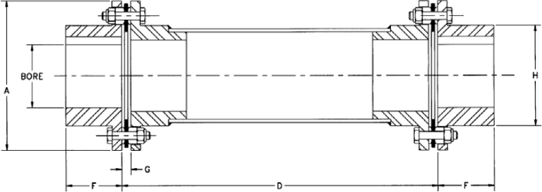
| Rated Misalignment: 0.7 Deg/Disc | Material Classes | |||||
|---|---|---|---|---|---|---|
| Class | Size | |||||
| Hub Types | Sizes | Ordering: B5 Series couplings are sold as complete assemblies. Please specify hub types and bore sizes, DBSE (D) dimension, speed for dynamic balancing, and material class. A coupling will be configured to meet your specifications. | A | 33-78 | ||
| BH | 33-78 | B | 33-78 | |||
| C | 38-63 | |||||
| E | N/A | |||||
| Size | Dimensions in Inches* | Max DBSE (D Inches) for RPM Shown | ||||||||||
|---|---|---|---|---|---|---|---|---|---|---|---|---|
| Max Bore | A | Dmin | F | G | H | |||||||
| 1800 | 1500 | 1200 | 900 | 750 | 600 | |||||||
| 33 | 2.25 | 4.69 | 4.25 | 1.75 | 0.285 | 3.14 | 79 | 87 | 97 | 112 | 122 | 137 |
| 38 | 3.00 | 5.87 | 6.00 | 2.25 | 0.335 | 4.13 | 97 | 107 | 119 | 137 | 150 | 168 |
| 43 | 3.25 | 6.70 | 7.00 | 2.50 | 0.465 | 4.63 | 103 | 113 | 126 | 146 | 160 | 178 |
| 48 | 3.75 | 7.50 | 7.50 | 2.75 | 0.495 | 5.40 | 113 | 125 | 139 | 160 | 175 | 196 |
| 53 | 3.88 | 7.87 | 7.50 | 2.88 | 0.520 | 5.65 | 113 | 125 | 139 | 160 | 175 | 196 |
| 58 | 4.25 | 9.00 | 7.50 | 3.25 | 0.555 | 6.22 | 123 | 136 | 151 | 170 | 186 | 208 |
| 63 | 4.88 | 10.00 | 7.50 | 3.38 | 0.600 | 7.14 | 123 | 136 | 151 | 170 | 186 | 208 |
| 68 | 5.00 | 10.75 | 8.00 | 3.75 | 0.849 | 7.33 | 130 | 142 | 159 | 183 | 201 | 225 |
| 73 | 5.25 | 12.50 | 10.00 | 5.13 | 1.000 | 7.80 | 130 | 142 | 159 | 183 | 201 | 225 |
| 78 | 6.50 | 14.90 | 10.00 | 6.38 | 0.940 | 9.50 | 148 | 162 | 181 | 209 | 228 | 257 |
| Size | HP per 100 RPM | Rated Torque (LB. IN.) | Peak O/L Torque (LB. IN.) | Weight (LBS.) | WR2 (LB. IN.2) | Tors. Stiffness 106 (LB. IN./RAD) | Free End Float +/- Inch | |||
|---|---|---|---|---|---|---|---|---|---|---|
| 1.0 S.F | At D = 20” | Add Per IN. of D | At D = 20” | Add Per IN. of D | K Factor | Y Factor | ||||
| 33 | 4.84 | 3,050 | 6,100 | 14.4 | 0.20 | 32.7 | 0.29 | 0.48 | 12.0 | 0.060 |
| 38 | 10.08 | 6,350 | 12,700 | 29.1 | 0.39 | 113 | 1.28 | 1.77 | 51.9 | 0.084 |
| 43 | 19.84 | 12,500 | 25,000 | 41.0 | 0.44 | 210 | 1.88 | 2.89 | 76.4 | 0.090 |
| 48 | 26.98 | 17,000 | 34,000 | 60.0 | 0.52 | 402 | 3.10 | 4.57 | 126 | 0.108 |
| 53 | 38.10 | 24,000 | 48,000 | 67.4 | 0.52 | 494 | 3.10 | 5.52 | 126 | 0.108 |
| 58 | 53.97 | 34,000 | 68,000 | 85.5 | 0.63 | 874 | 5.43 | 8.44 | 220 | 0.118 |
| 63 | 76.19 | 48,000 | 96,000 | 108 | 0.63 | 1340 | 5.43 | 9.52 | 220 | 0.140 |
| 68 | 114.29 | 72,000 | 144,000 | 140 | 1.15 | 1940 | 13.37 | 19.9 | 543 | 0.144 |
| 73 | 198.41 | 125,000 | 250,000 | 210 | 1.15 | 3860 | 13.37 | 25.0 | 543 | 0.156 |
| 78 | 369.84 | 233,000 | 466,000 | 355 | 1.95 | 9640 | 37.32 | 59.3 | 1510 | 0.165 |
| Note: | Note: 1) Weight, WR2 and torsional stiffness values shown are for BH hubs at maximum bore size. 2) To calculate torsional stiffness for a given spacer length, let L=D - 20” torsional stiffness = 1/[(1/K) + (L/Y)] | |||||||||
The HFTH series is designed for heavy duty applications that cannot use the A5 or B5 series. These include high torque and engine driven applications. The HFTH uses a welded tubular spacer assembly. Flex discs are high strength alloy steel. Stainless steel flex discs are optional. Dynamic balancing of the spacer assembly is included. The HFTH is made-to-order to any custom spacer length. Large tube designs are also available.
| Hub Types | Sizes | 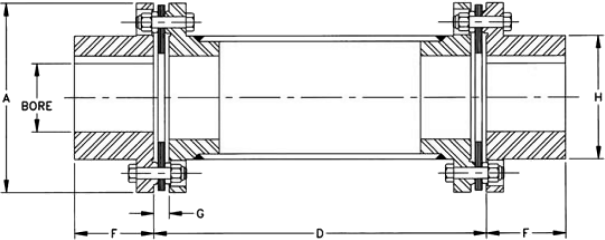 | |
|---|---|---|---|
| C.I. | 35-160 | ||
| STL | 35-160 | ||
| Ordering: HFTH Series couplings are sold as complete assemblies. Please specify hub speed for dynamic balancing. A coupling will be configured to meet your specifications. | |||
| Rated Misalignment: 0.3 Deg/Disc | |||
| Size | Dimensions in Inches | Max DBSE (D Inches) for RPM Shown | |||||||||||
|---|---|---|---|---|---|---|---|---|---|---|---|---|---|
| Max Bore | A | Dmin | F | G | H | ||||||||
| Iron | Steel | 1800 | 1500 | 1200 | 900 | 750 | 600 | ||||||
| 35 | 3.62 | 3.81 | 9.12 | 10.0 | 3.75 | 0.66 | 6.12 | 114 | 124 | 139 | 161 | 176 | 197 |
| 42 | 4.25 | 4.50 | 11.0 | 10.0 | 4.25 | 0.81 | 7.00 | 128 | 140 | 157 | 182 | 198 | 222 |
| 45 | 4.50 | 4.75 | 11.87 | 10.0 | 4.50 | 0.87 | 7.43 | 130 | 143 | 160 | 185 | 201 | 226 |
| 50 | 5.12 | 5.50 | 13.43 | 10.0 | 5.00 | 1.06 | 8.37 | 139 | 153 | 171 | 197 | 215 | 242 |
| 55 | 5.62 | 6.25 | 15.00 | 10.0 | 5.50 | 1.25 | 9.50 | 145 | 159 | 178 | 206 | 224 | 252 |
| 60 | 6.50 | 7.12 | 16.75 | 15.0 | 6.25 | 1.34 | 10.50 | 153 | 168 | 188 | 217 | 237 | 266 |
| 70 | 7.00 | 7.87 | 18.93 | 15.0 | 7.00 | 1.50 | 11.75 | 161 | 176 | 197 | 228 | 250 | 279 |
| 75 | 7.75 | 8.75 | 20.62 | 15.0 | 7.25 | 1.55 | 13.00 | 172 | 189 | 211 | 244 | 267 | 299 |
| 80 | 8.00 | 9.12 | 22.37 | 15.0 | 7.75 | 1.56 | 13.75 | 182 | 199 | 222 | 257 | 282 | 315 |
| 85 | 8.50 | 9.62 | 25.75 | 20.0 | 8.25 | 1.62 | 14.50 | CONSULT ABSSAC | |||||
| 92 | 10.00 | 11.00 | 25.75 | 20.0 | 9.00 | 1.75 | 15.87 | ||||||
| 105 | 10.50 | 12.00 | 29.25 | 20.0 | 10.50 | 1.75 | 20.00 | ||||||
| 160 | 16.00 | 17.00 | 33.50 | 20.0 | 12.00 | 2.25 | 24.00 | ||||||
| Size | HP per 100 RPM | Rated Torque (LB. IN.) | Peak O/L Torque (LB. IN.) | Weight (LBS.) | WR2 (LB. IN.2) | Tors. Stiffness 106 (LB. IN./RAD) | Free End Float +/- Inch | |||
|---|---|---|---|---|---|---|---|---|---|---|
| 1.0 S.F | At D = 20” | Add Per IN. of D | At D = 20” | Add Per IN. of D | K Factor | Y Factor | ||||
| 35 | 69.84 | 44,000 | 66,000 | 111 | 0.81 | 1,040 | 5 | 9 | 190 | 0.056 |
| 42 | 115.9 | 73,000 | 109,500 | 186 | 1.14 | 2,520 | 13 | 21 | 537 | 0.067 |
| 45 | 157.1 | 99,000 | 148,500 | 201 | 1.14 | 3,370 | 13 | 23 | 537 | 0.072 |
| 50 | 203.2 | 128,000 | 192,000 | 311 | 1.31 | 6,430 | 20 | 38 | 810 | 0.082 |
| 55 | 300.0 | 189,000 | 283,500 | 374 | 1.95 | 10,100 | 37 | 67 | 1,510 | 0.092 |
| 60 | 414.3 | 261,000 | 391,500 | 556 | 3.21 | 18,600 | 75 | 110 | 3,020 | 0.102 |
| 70 | 658.7 | 415,000 | 622,500 | 769 | 3.21 | 33,000 | 75 | 134 | 3,020 | 0.115 |
| 75 | 846.0 | 533,000 | 799,500 | 948 | 4.13 | 49,000 | 158 | 252 | 6,430 | 0.125 |
| 80 | 1087 | 685,000 | 1,027,500 | 1260 | 4.13 | 78,900 | 158 | 265 | 6,430 | 0.136 |
| 85 | 1316 | 829,000 | 1,243,500 | CONSULT ABSSAC | 0.140 | |||||
| 92 | 1651 | 1,040,000 | 1,560,000 | 0.166 | ||||||
| 105 | 1984 | 1,250,000 | 1,875,000 | 0.170 | ||||||
| 160 | 3175 | 2,000,000 | 3,000,000 | 0.250 | ||||||
| Note: | 1) Weight, WR2 and torsional stiffness values shown are for AJ hubs at maximum bore size. 2) To calculate torsional stiffness for a given spacer length, let L=D - Dmin torsional stiffness = 1/[(1/K) + (L/Y)] | |||||||||
TrueTube composite tubes are high-strength, lightweight torque tubes for long span drive shafts. These tubes are filament wound carbon or glass fibre construction in an oven cured epoxy matrix. TrueTube composites offer the following advantages over steel tubing:
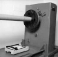
Longer Spans
TrueTube composite tubes have a higher stiffness to weight ratio than steel tubing. That increases the critical speed of the tubing and allows longer spans without centre bearings.
Light Weight
TrueTube drive shafts weigh up to 80% less than equivalent steel driveshafts. That means better balance and reduced vibration. Bearing life may be improved by minimising overhung weight.
Design Flexibility
TrueTube composite tubes may be custom designed to meet your requirements for torsional stiffness, critical speed or torque capacity. With TrueTube, a designer can tune torsional or lateral critical speeds out of a machine system.
All TrueTube products include an ultraviolet barrier that is wound into the structure of the tube before it is cured. This UV barrier eliminates the need for paints or other protective coatings and results in a smooth, durable finish that other composite tubes don’t offer. TrueTube products are cured in an enclosed oven to assure consistent strength and quality. Design data is shown below for standard series tubes. Standard series tubes are designed for maximum length at moderate torques. High torque designs are also available.
| Model Number | Tube I.D. Inches | Tube O.D. Inches | Sleeve O.D. I nches | Rated Torque LB*IN | Tube Weight (LB/IN) | Tors. Stiffness 106 (LB. IN./RAD) | Max DBSE (D Inches) | Max Tube Length Inches | |||
|---|---|---|---|---|---|---|---|---|---|---|---|
| 2000 RPM | 1800 RPM | 1500 RPM | 1000 RPM | ||||||||
| SERIES SL – ALL CARBON CONSTRUCTION | |||||||||||
| SL2.0 | 2.00 | 2.30 | 2.40 | 6,500 | 0.05 | 1.26 | 90 | 95 | 104 | 127 | 82 |
| SL3.0 | 3.00 | 3.25 | 3.50 | 12,000 | 0.08 | 3.61 | 110 | 116 | 127 | 155 | 128 |
| SL4.0 | 4.00 | 4.23 | 4.50 | 22,000 | 0.11 | 8.60 | 127 | 134 | 147 | 180 | 145 |
| SL6.0 | 6.00 | 6.25 | 6.63 | 42,000 | 0.20 | 34.4 | 152 | 160 | 175 | 214 | 177 |
| SL8.0 | 8.00 | 8.25 | 8.63 | 63,000 | 0.24 | 80.2 | 180 | 190 | 208 | 255 | 192 |
| SL10.0 | 10.00 | 10.25 | 10.75 | 80,000 | 0.32 | 155 | 199 | 210 | 230 | 281 | 232 |
| SL12.0 | 12.00 | 12.25 | 12.75 | 100,000 | 0.38 | 258 | 215 | 227 | 249 | 304 | 232 |
| SERIES SS – CARBON/GLASS CONSTRUCTION | |||||||||||
| SS2.0 | 2.00 | 2.30 | 2.40 | 5,500 | 0.06 | 0.97 | 79 | 83 | 91 | 111 | 82 |
| SS3.0 | 3.00 | 3.25 | 3.50 | 10,500 | 0.08 | 2.86 | 97 | 102 | 112 | 137 | 128 |
| SS4.0 | 4.00 | 4.23 | 4.50 | 22,000 | 0.12 | 7.28 | 112 | 118 | 129 | 158 | 145 |
| SS6.0 | 6.00 | 6.25 | 6.63 | 42,000 | 0.20 | 26.4 | 135 | 142 | 155 | 190 | 177 |
| SS8.0 | 8.00 | 8.25 | 8.63 | 58,000 | 0.28 | 57.3 | 151 | 160 | 176 | 216 | 192 |
| SS10.0 | 10.00 | 10.25 | 10.75 | 73,000 | 0.34 | 115 | 173 | 183 | 200 | 245 | 232 |
| SS12.0 | 12.00 | 12.25 | 12.75 | 88,000 | 0.42 | 206 | 189 | 199 | 218 | 267 | 232 |
| SERIES LS – ALL GLASS CONSTRUCTION | |||||||||||
| LS2.0 | 2.00 | 2.30 | 2.40 | 5,000 | 0.07 | 0.75 | 66 | 70 | 77 | 94 | 82 |
| LS3.0 | 3.00 | 3.25 | 3.50 | 10,000 | 0.09 | 2.06 | 80 | 84 | 92 | 113 | 128 |
| LS4.0 | 4.00 | 4.23 | 4.50 | 18,000 | 0.14 | 5.04 | 93 | 98 | 107 | 131 | 145 |
| LS6.0 | 6.00 | 6.25 | 6.63 | 39,000 | 0.23 | 18.9 | 110 | 116 | 127 | 155 | 177 |
| LS8.0 | 8.00 | 8.25 | 8.63 | 51,000 | 0.30 | 43.0 | 128 | 135 | 148 | 181 | 192 |
| LS10.0 | 10.00 | 10.25 | 10.75 | 64,000 | 0.37 | 86.0 | 142 | 150 | 164 | 201 | 232 |
| LS12.0 | 12.00 | 12.25 | 12.75 | 77,000 | 0.46 | 149 | 155 | 163 | 178 | 218 | 232 |
| Note: | 1) Torque ratings at 100% humidity and 200 deg.f. 2) Max rpm values shown are calculated at 75% of first critical speed. 3) Torsional stiffness shown is per inch of tube length. Actual stiffness = torsional stiffness/tube length (in.) | ||||||||||
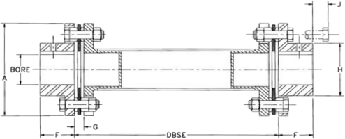
Form-Flex flexible couplings may be mated to TruTube composite tubes for use as long floating shaft couplings. All types and most sizes of Form-Flex couplings can be mated to TrueTube composites. Common combinations are shown below.
| Size | Rated Torque | Hp per 100 RPM | Coupling Product No. | Maximum DBSE - Inches | Dimensions in Inches | ||||||||
|---|---|---|---|---|---|---|---|---|---|---|---|---|---|
| LB IN | Max | 1800 RPM | 1500 RPM | Maximum Bore | A | F | G | H | J | ||||
| Std Hub | AZ Hub | ||||||||||||
| A520 | 2,200 | 3.49 | A520-CS2G | 83 | 70 | 77 | 1.625 | 2.125 | 4.08 | 1.32 | 0.34 | 2.40 | 2.30 |
| A520-CS2R | 83 | 83 | 83* | 2.30 | |||||||||
| A525 | 3,800 | 6.03 | A525-CS2G | 83 | 70 | 77 | 2.000 | 2.375 | 4.95 | 1.62 | 0.45 | 2.80 | 2.30 |
| A525-CS2R | 83 | 83 | 83* | 2.30 | |||||||||
| A530 | 6,930 | 11.00 | A530-CS3R | 128 | 102 | 112 | 2.375 | 2.875 | 5.63 | 1.88 | 0.47 | 3.30 | 3.25 |
| A530-CS3B | 128 | 116 | 127 | 3.25 | |||||||||
| A535 | 11,340 | 18.00 | A535-CS4R | 146 | 118 | 129 | 2.875 | 3.750 | 6.63 | 2.25 | 0.55 | 4.15 | 4.25 |
| A535-CS4B | 146 | 134 | 146* | 4.25 | |||||||||
| A535-CS6R | 179 | 142 | 155 | 6.30 | |||||||||
| A535-CS6B | 179 | 160 | 175 | 6.30 | |||||||||
| A535-CS8R | 196 | 175 | 191 | 8.31 | |||||||||
| A535-CS8B | 196 | 190 | 207* | 8.31 | |||||||||
| A540 | 18,270 | 29.00 | A540-CS4R | 146 | 118 | 129 | 3.250 | 4.000 | 7.63 | 2.5 | 0.6 | 4.65 | 4.25 |
| A540-CS4B | 146 | 134 | 146* | 4.25 | |||||||||
| B558 | 34,000 | 54.00 | B558-CS6R | 179 | 142 | 155 | 3.75 | – | 9.00 | 2.75 | 0.56 | 5.43 | 6.30 |
| B558-CS6B | 179 | 160 | 175 | 6.30 | |||||||||
| B558-CS6X | 182 | 165 | 181 | 6.30 | |||||||||
| B558-CS8R | 196 | 175 | 191 | 8.31 | |||||||||
| B558-CS8B | 196 | 190 | 207 | 8.31 | |||||||||
| B558-CS10R** | 236 | 206 | 224 | 10.31 | |||||||||
| B558-CS10B** | 236 | 210 | 230 | 10.31 | |||||||||
Quick Selection Guide for Cooling Tower Applications | Composite Tube Construction | ||||||||
| 1800 RPM | Coupling Model | 1500 RPM | Model Code | Tube Material of Construction | |||||
|---|---|---|---|---|---|---|---|---|---|
| DBSE | MAX HP | MAX HP | DBSE | ||||||
| 70” | 30 | A520-S2G | 25 | 77” | G | Glass | |||
| 50 | HD4-CS2G*** | 42 | R | Carbon/Glass Hybrid | |||||
| 50 | A525-CS2G | 42 | B | Standard Carbon | |||||
| 83” | 30 | A525-CS2R | 25 | 83” | X,Z | High Modulus Carbon | |||
| 50 | HD4-CS2R*** | 42 | The model code is the last letter in the coupling model number. The number xx in the tube model number CSxxB denotes the nominal tube id. | ||||||
| 50 | A525-CS2R | 42 | |||||||
| 102” | 100 | A530-CS3R | 83 | 112” | |||||
| 116” | 100 | A530-CS3B | 83 | 127” | |||||
| 118” | 150 | A535-CS4R | 125 | 129” | Material Class | Material Used | |||
| 250 | A540-CS4R | 208 | Hub | Hardware | Spacer Flanges | ||||
| 134” | 150 | A535-CS4B | 125 | 146” | A | Steel | Steel | Composite or Steel | |
| 250 | A540-CS4B | 208 | B | Steel Zinc PLT | Steel, Zinc PLT | Composite or Zinc Plated Steel | |||
| 142” | 150 | A535-CS6R | 125 | 155” | C | 304SS | |||
| 400 | B558-CS6R | 333 | E | 304SS | 304SS | Composite or 304SS | |||
| 160” | 150 | A535-CS6B | 125 | 175” | Metal spacer flanges used if composite is not available. | ||||
| 400 | B558-CS6B | 333 | |||||||
| 165” | 400 | B558-CS6X | 333 | 181” | |||||
| 175” | 150 | A535-CS8R | 125 | 191” | Notes: | ||||
| 400 | B558-CS8R | 333 | * | Length is restricted by available mandrels for winding composite tubes. Consult factory for longer lengths. | |||||
| 190” | 150 | A535-CS8B | 125 | 207” | |||||
| 400 | B558-CS8B | 333 | ** | Tube diameter is larger than coupling “A” diameter. Consult factory for coupling drawing. | |||||
| 206” | 400 | B558-CS10R | 333 | 224” | |||||
| 210” | 400 | B558-CS10B | 333 | 230” | *** | HD4-CS couplings are an all composite, high misalignment coupling. | |||
| 227” | 400 | B558-CS12B | 333 | 236” | |||||
| All selections use A 2.0 Service Factor | |||||||||
Form-Flex M series microcouplings are a more compact and lighter design than traditional A Series couplings. They are free from backlash and their high torsional stiffness makes them ideally suited for small servo and tachometer drives. Aluminium hub construction meets low inertia requirements while the bolted assembly provides superior life when compared to riveted types.
| Style MA | Style MB | Style MC |
|---|---|---|
| This coupling style is available in size 04 only. It features a machined spool type spacer. Custom length spacers are also available. | This coupling style features a minimum length block spacer. Standard flanged hubs are supplied with the coupling. Style MB is a good, general use coupling. | This style features the MB style minimum length spacer and an oversize bore capacity. The style MC provides the shortest coupling overall. |
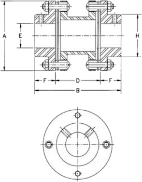 | 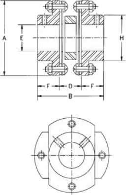 | 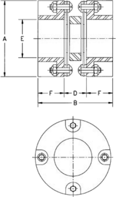 |
| Dimensions in Inches | Rated Torque (LB. IN.) | Peak O/L Torque (LB. IN.) | WR2 OZ (IN.2) | Torsional Stiffness (LB. IN./RAD) | Rated Mis-Alignment DEG/DISC | Free End Float (IN.) | ||||||||
|---|---|---|---|---|---|---|---|---|---|---|---|---|---|---|
| Style | Size | Max Bore | A | B | D DBSE | F | H | STD Set Screw Size | ||||||
| MA | 04 | 0.79 | 2.24 | 2.93 | 1.36 | 0.79 | 1.22 | M6 x 1.0 | 87 | 174 | 6.11 | 64.7 x 10^3 | 1.5 | 0.60 |
| MB | 02 | 0.38 | 1.26 | 1.39 | 0.45 | 0.47 | 0.71 | M4 x 0.7 | 17 | 34 | 0.29 | 2..9 x 10^3 | 1.5 | 0.40 |
| 03 | 0.63 | 1.65 | 1.80 | 0.54 | 0.63 | 1.02 | M4 x 0.7 | 35 | 70 | 1.33 | 14.9 x 10^3 | 1.5 | 0.50 | |
| 04 | 0.79 | 2.24 | 2.38 | 0.81 | 0.79 | 1.22 | M6 x 1.0 | 87 | 174 | 4.99 | 64.7 x 10^3 | 1.5 | 0.60 | |
| MC | 01 | 0.38 | 1.02 | 1.08 | 0.45 | 0.32 | - | M3 x 0.5 | 9 | 18 | 0.17 | 2.4 x 10^3 | 1.5 | 0.25 |
| 02 | 0.59 | 1.26 | 1.53 | 0.45 | 0.32 | - | M4 x 0.7 | 17 | 34 | 0.35 | 2.9 x 10^3 | 1.5 | 0.40 | |
| 03 | 0.79 | 1.65 | 1.53 | 0.54 | 0.50 | - | M4 x 0.7 | 35 | 70 | 1.34 | 14.9 x 10^3 | 1.5 | 0.50 | |
| Note: | Style MB04 coupling hubs will have round flanges as shown for type MA. | |||||||||||||
Repair kits consist of flex discs and all the necessary installation hardware. SINGLE REPAIR KITS have one set of flex discs and all required hardware. Two single repair kits are required for a double flexing coupling. DOUBLE REPAIR KITS have two sets of flex discs and all required hardware. HARDWARE KITS have all the components of a repair kit except the flex discs. FLEX DISCS are also sold individually.
A Series (4 bolt) Coupling Parts | |||||||||
| Kit Type | Repair | Hardware | Repair | Hardware | Repair | Hardware | Flex Disc | ||
|---|---|---|---|---|---|---|---|---|---|
| Sgl/Dbl | Single | Double | Double | ||||||
| Used On Mat'l Class | AA, AK, AP, AR, A5, A7 | AX | AY | ALL | |||||
| A,B | C,E | A,B | C,E | A,B | A,B | A,B | A,B | ALL | |
| 05 | A05RKA | ... | A05HKA | ... | AX05RKA | AX05HKA | AY05RKA | AY05HKA | A0054101 |
| 10 | A10RKA | ... | A10HKA | ... | AX10RKA | AX10HKA | AY10RKA | AY10HKA | A0104101 |
| 15 | A15RKA | A15RKE | A10HKA | A15HKE | AX15RKA | AX15HKA | AY15RKA | AY15HKA | A0154101 |
| 20 | A20RKA | A20RKE | A20HKA | A20HKE | AX20RKA | AX20HKA | AY20RKA | AY20HKA | A0204101 |
| 25 | A25RKA | A25RKE | A25HKA | A25HKE | AX25RKA | AX25HKA | AY25RKA | AY25HKA | A0254101 |
| 30 | A30RKA | A30RKE | A30HKA | A30HKE | AX30RKA | AX30HKA | ... | ... | A0304101 |
| 35 | A35RKA | A35RKE | A35HKA | A35HKE | AX35RKA | AX35HKA | ... | ... | A0354101 |
| 40 | A40RKA | A40RKE | A10HKA | A15HKE | AX40RKA | AX40HKA | ... | ... | A0404101 |
| 45 | A45RKA | A45RKE | A45HKA | A45HKE | AX45RKA | AX45HKA | ... | ... | A0454101 |
B Series (4 bolt) Coupling Parts (EXCEPT BA) | |||||||||
| Kit Type | Repair | Hardware | Repair | Hardware | Repair | Hardware | Flex Disc | ||
|---|---|---|---|---|---|---|---|---|---|
| Sgl/Dbl | Single | Single | Double | ||||||
| Used On Mat'l Class | BH, BP, B5 | BF | BY | ALL | |||||
| A,B | C | A,B | C | A,B | A,B | A,B | A,B | ALL | |
| 15 | ... | ... | ... | ... | BF15RKA | BF15HKA | ... | ... | A0154101 |
| 20 | ... | ... | ... | ... | BF20RKA | BF20HKA | ... | ... | A0204101 |
| 33 | B033RKA | ... | B033HKA | ... | BF33RKA | BF33HKA | BY33RKA | BY33HKA | B0334101 |
| 38 | B038RKA | B038RKE | B038HKA | B038HKE | BF38RKA | BF38HKA | BY38RKA | BY38HKA | B0384101 |
| 43 | B043RKAB | B043RKE | B043HKAB | B043HKEB | BF43RKAB | BF43HKAB | BY43RKAB | BY43HKA | B0434101 |
| 48 | 048RKA | B048RKE | 048HKA | 048HKE | F48RKA | F48HKA | Y48RKA | BY48HKA | B0484101 |
| 53 | B053RKA | B053RKE | B053HKA | B053HKE | BF53RKA | BF53HKA | BY53RKA | BY53HKA | B0534101 |
| 58 | B058RKA | B058RKE | B058HKA | B058HKE | BF58RKA | BF58HKA | BY58RKA | BY58HKA | B0584101 |
| 63 | B063RKA | B063RKE | B063HKA | B063HKE | BF63RKA | BF63HKA | BY63RKA | BY63HKA | B0634101 |
| 68 | B068RKA | ... | B068HKA | ... | BF68RKA | BF68HKA | BY68RKA | BF68HKA | B0684101 |
| 73 | B073RKA | ... | B073HKA | ... | BF73RKA | ... | BY73RKA | ... | B0734101 |
| 76 | B078RKA | ... | B078HKA | .... | BF78RKA | ... | BY78RKA | ... | B0784101 |
8 Bolt Coupling Parts (EXCEPT DA AND DP) | |||||||||
| Coupling Size | HH, HSH, FSH, HFTH | ||||||||
|---|---|---|---|---|---|---|---|---|---|
| Double Repair Kit | Single Hardware Kit | Flex Disc | Bolt | Washer | Nut | ||||
| STD Disc | SS Disc | STD | SS | ||||||
| 22 | D22-DF | D22-DF-SS | D22-BNW | D22-5 | D22-5-SS | D22-6H | D22-7 | D22-6N | |
| 26 | D26-DF | D26-DF-SS | D26-BNW | D26-5 | D26-5-SS | D26-6H | D26-7 | D26-6N | |
| 31 | D31-DF | D31-DF-SS | D31-BNW | D31-5 | D31-5-SS | D31-6H | D31-7 | D31-6N | |
| 35 | D35-DF | D35-DF-SS | D35-BNW | D35-5 | D35-5-SS | D35-6H | D35-7 | D35-6N | |
| 37 | D37-DF | D37-DF-SS | D37-BNW | D37-5 | D37-5-SS | D37-6H | D37-7 | D37-6N | |
| 42 | D42-DF4* | D42-DF4-SS* | D42-BNW4* | D42-5 | D42-5-SS | D42-6H4* | D42-7 | D42-6N | |
| 45 | D45-DF4* | D45-DF4-SS* | D45-BNW4* | D45-5 | D45-5-SS | D45-6H4* | D45-7 | D45-6N | |
| 50 | D50-DF4* | D50-DF4-SS* | D50BNW4* | D50-5 | D50-5-SS | D50-6H4* | D50-7 | D50-6N | |
| 55 | D55-DF4* | D55-DF4-SS* | D55-BNW4* | D55-5 | D55-5-SS | D55-6H4* | D55-7 | D55-6N | |
| 60 | D60-DF4* | D60-DF4-SS* | D60-BNW4* | D60-5 | D60-5-SS | D60-6H4* | D60-7 | D60-6N | |
| 70 | D70-DF | D70-DF-SS | D70-BNW | D70-5 | D70-5-SS | D70-6H | D70-7 | D70-6N | |
| 75 | D75-DF4* | D75-DF4-SS* | D75BNW4* | D75-5 | D75-5-SS | D75-6H4* | D75-74* | D75-6N4* | |
| 80 | D80-DF4* | D80-DF4-SS* | D80BNW4* | D80-5 | D80-5-SS | D80-6H4* | D80-7 | D80-6N | |
| 85 | D85-DF | D85-DF-SS | D85-BNW | D85-5 | D85-5-SS | D85-6H | D85-7 | D85-6N | |
| 92 | D92-DF | D92-DF-SS | D92-BNW | D92-5 | D92-5-SS | D92-6H | D92-7 | D92-6N | |
| *Items marked * have new style bolts. Bolt head hex may not fit FSH type flywheel adapters manufactured 1994 or earlier. To received Old Style Bolts, delete the “4” from these part numbers. | |||||||||
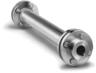
Designed specifically as a connection for cooling tower applications and other drives requiring long shaft spans. Form-Flex couplings with TrueTube composite tubing weigh less than half of its steel counterpart and can span shaft separations of up to 240 inches. They are easy to handle, install and maintain. TrueTube composites are extremely corrosion resistant and are custom designed to provide the optimum combination of torsional strength and lateral stiffness for cooling tower drive applications. TB Wood's proprietary composite flange design transmits torque reliably from the metal outboard hubs to the composite flange and into the TrueTube composite tube.
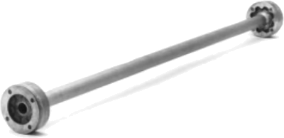
The traditional A5 design features all metal construction. It can be ordered to meet any custom spacer length. A wide variety of materials and finishes is available.
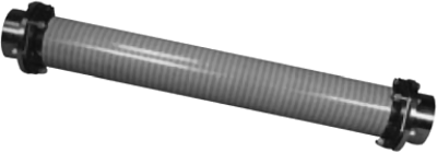
HD elastometric couplings and TrueTube composites are combined into a high misalignment, all composite coupling. These couplings are easy to install and align. Their high misalignment capacity makes them ideal for smaller, wood framed and fibreglass towers.
Please contact our technical sales department for further details.
Name | Tel | |||||
E-Mail | ||||||
Company | Fax | |||||
Address | ||||||
| Operating Information | ||||||
|---|---|---|---|---|---|---|
| 1. Drive* a or b. Direction c. Continuousd. Reversing e. Stop-Startcycles/sec f. RPMg. Manual 2. Service*a. Operating Torquelbin or Nm. b. Maximum Torquelbin or Nm. 3. Misalignments*a. Angular b. Parallel c. Axial Compression/Extensionsin. or mm d. Skew - please provide sketch | 4. Torsional Rate* deg/lb.in. or deg/Nm a. less thanb. equal toc. greater than 5. Inertial Limitations / Mass Moment of Inertiadeg/lb.in. or deg/Nm a. less thanb. equal toc. greater than 6. Weightoz. or gm a. less thanb. equal toc. greater than 7. Environmenta. Temperature°F or °C b. Corrosive c. Abrasive | |||||
| Flexure and Component Layout | ||||||
8a.* Preferred Outside Diameterin. or mm Maximum Outside Diameterin. or mm | b.* Preferred Lengthin. or mm Maximum Lengthin. or mm | |||||
c. *Driver Description | 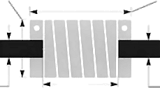 | d. *Driver Description | ||||
e.*Shaft Diameter in. or mm | g.*Shaft to Shaft in. or mm | f.*Shaft Diameter in. or mm | ||||
| 9. Bore Tolerance | ATTACHMENTS | 12.Material | ||||
a. Commercial +.002 in. -.000 in. or +.05 mm -.00mm b. Precision +.0005 in. -.0000 in. or +.015 mm -.000mm | 10. Driver* | 11. Driven* | 7075-T6 Aluminium Alloy 17-4 PH Stainless Steel Other | |||
| a | Integral Clamp | a | ||||
| b | 2 Set Screws at 120° | b | ||||
| c | 2 Set Screws at 90° | c | ||||
| d | 1 Set Screw | d | ||||
| e | Roll Pin in. or mm | e | 13.Production Quantity | |||
| f | Dowel Pin in. or mm | f | 1-24 25-100 100+ | * Items marked with an asterisk are essential for optimum design. | ||
| g | Keyway type size | g | ||||
| h | Other/describe below | h | ||||
Type of equpiment | ||||||
Comments | ||||||
"ABSSAC" is a registered trade mark 2375859
All rights are reserved.
The use of this catalogue is made available to you by Abssac Limited. The exclusive right to control the use of the copyright and trademarks on this site is controlled by Abssac Limited. These may not be copied, reproduced, published, distributed, modified or otherwise used in any form including electronic copying without the express permission of Abssac Limited. Abssac Limited has made all reasonable endeavor to ensure that the material on this site is accurate. You agree that Abssac Limited, nor any other person involved in creating or providing this catalogue shall be liable for any indirect or consequential damage arising from the use of any information contained in this catalogue.
The information contained in this catalogue is provided 'as is' without warranty of any kind, either expressed or implied. Abssac Limited assumes no responsibility for errors or omissions in this catalogue or other documents which are reference by or linked to this catalogue. This catalogue could include technical or other inaccuracies including typographical errors. Updates and changes are periodically added to the information herein; these changes will be incorporated in new editions of this catalogue. Abssac Limited may make improvements and/or changes in the product(s) or service(s) described in this publication at any time. You agree that the above terms represent the entire basis of the agreement between us, upon which you are permitted to enter this site and you agree that all relations between us are subject to the Law of England and Wales.