Shaft couplings manufactured from plastic offer an excellent low cost equivalent to aluminium shaft couplings especially where the torque requirement is lower.
This product range offers you a quality range of plastic injection moulded shaft couplings giving high torsional stiffness combined with exceptional durability to shaft misalignment. There are two basic designs called UJ and GJ. Type UJ is for lighter usage and smaller angular and parallel shaft offsets, whilst type GJ, with its two flexible elements, is ideal for medium usage. The UJ & GJ series are available in a large variety of bore combinations from 1.5mm to 12.00mm.
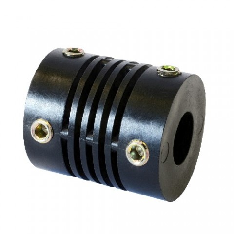
If you require a low cost, reliable, zero backlash shaft coupling, Abssac has the answer with its range of injection moulded flexible shaft couplings. Using the latest injection moulding techniques Abssac is able to supply a low cost, one piece, flexible shaft coupling to suit most rotary applications. Many people have asked us to supply a plastic shaft coupling for those types of application where a aluminium or stainless steel shaft coupling is just over kill for the application.
What you get is the use of the most advanced plastics compositions in a high quality, single piece construction at a low cost. There are three basic models capable of transmitting torques up to 8 kg/cm through 8 degrees of angular misalignment. Some of the plastics compositions are also reinforced with glass fibre to give it a higher torque capability.


If you require further technical information, please do not hesitate to contact our sales engineers who will be more than happy to help you with your selection.
