Linear guides and rails

At Abssac, we concentrate on the flanged mount and square mount versions of linear guides. These items are in stock and have proven to be the best linear guide solution when teamed up with any of our  ball and  lead screw products. Dimensional data for these models can be accessed by the buttons above but we do encourage you to contact our knowledgeable sales team who can help you with the right selection..

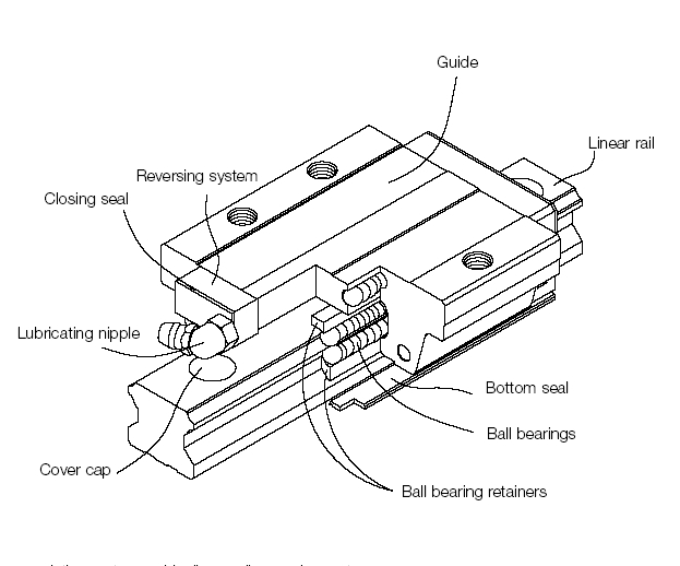
By primarily using a four ball path design, within the slide, allows the guides to accept up to 30% more load and up to 30% stiffer than similar products in the market. An added bonus is that the ball bearings are retained within the housing so that should the guides come off the end of the rail, you will not be faced with all the ball bearings falling out. From experience, we know that this advantage can also significantly aid in the final assembly.

 
Linear guides and rails Image

Typical Guide applications include;

  • Grinders
  • NC Lathes
  • Machining centres
  • Precision milling
  • Automation technology
  • Transportation technology
  • Measuring applications
  • Machines that require a high level of positional accuracy
  • Ideal for use with our Transport ball screw ranges

We also offer the advantage of supplying lightly pre-loaded heavy duty or extra heavy duty guide models to suit individual applications. When compared to other slide mechanisms such as dovetail slides, efficiency is far greater. The linear guides can carry loads in both horizontal and vertical directions. Please also note that the  rails are pre drilled for ease of fitting and can be delivered cut to your desired length at no extra cost. Please note that all guides come with dust proofing  seals at each end.


Available rail widths from 15mm to 65mm cater from the lightest to the heaviest load.  If your application requires an accurate support and guide, our ex-stock range of linear rails may be the answer to your design challenges. Rails can be supplied from 100mm to 4000mm in length and in some cases can be attached to the application from beneath.

Typical performance data

HG Series 25,30,35 Normal High Precision Super precision Ultra precision
Accuracy Class +/- 0.1mm +/- 0.04mm +/- 0 +/- 0 +/-0
Height Tolerance H1 +/- 0.1mm +/- 0.04mm + 0 / -0.04mm +0/0.02mm +0/0.01mm
Width Tolerance N1 +/-0.1mm +/- 0.04mm +0 / -0.04mm +0/0.02mm +0/-0.01mm


For Product Advice Call Us Now 01386 421005


Subscribe to Newsletter

Business / Name: Subscribe to Newsletter
Email:
Lists: ABSSAC Newsletter 


Flanged Mount Slide

HGW Diagram

Model INSTALLATION
DIMENSIONS (mm)
DIMENSIONS OF THE GUIDE (mm) DIMENSIONS OF
THE GUIDE RAIL (mm)
SCREWS FOR RAIL (mm) DYNAMIC LOAD Cdyn (N) STATIC LOAD C0 (N) STATIC MOMENT MASS
H H1 N W B B1 C L1 L G M T T1 T2 H2 H3 WR HR D h d P Mo (Nm) Mx (Nm) MY (Nm) Guide (kg) Rail (kg/m)
HGW15CC 24 4.3 16 47 38 4.5 30 39.4 61.4 5.3 M5 6 8.9 6.95 4.5 5.5 15 15 7.5 5.3 4.5 60 M4x16 11380 25310 170 150 150 0.17 1.45
HGW20CC
HGW20HC
30 4.6 21.5 63 53 5 40 50.5 65.2 77.5 90.3 12 M6 8 10 9.5 6 7 20 17.5 9.5 8.5 6 60 M5x16 17750
21180
37840 48840 380 480 270
470
270
470
0.51
0.52
2.21
HGW25CC
HGW25HC
36 5.5 23.5 70 57 6.5 45 58 78.6 83 103.6 12 M8 8 14 10 6 9 23 22 11 9 7 60 M6x20 26480 32750 56190 76000 640 870 510
880
510
880
0.78
0.80
3.21
HGW30CC
HGW30HC
42 6 31 90 72 9 52 70 93 97.4 120.4 12 M10 8.5 16 10 6.5 10.8 28 26 14 12 9 80 M8x25 38740 47270 83060 110130 1060 1400 850
1470
850
1470
1.42
1.44
4.47
HGW35CC
HGW35HC
48 7.5 33 100 82 9 62 80 105.8 112.4 138.2 12 M10 10.1 18 13 9 12.6 34 29 14 12 9 80 M8x25 49520 60210 102870 136310 1730 2290 1200
2080
1200
2080
2.03
2.06
6.3
HGW45CC
HGW45HC
60 9.5 37.5 120 100 10 80 97 128.8 138 169.8 12.9 M12 15.1 22 15 8.5 20.5 45 38 20 17 14 102 M12x35 77570 94540 155930 207120 3010 4000 2350
4070
2350
4070
3.54
3.69
10.41
HGW55CC
HGW55HC
70 13 43.5 140 116 12 95 117.7 155.8 165.7 203.8 12.9 M14 17.5 26.5 17 12 19 53 44 23 20 16 120 M14x45 114440 139350 227810 301260 5660 7490 4060
7010
4060
7010
5.38
5.96
15.08
HGW65CC
HGW65HC
90 15 53.5 170 142 14 110 144.2 203.6 198.2 257.6 12.9 M16 25 37.5 23 15 15 63 53 26 22 18 150 M16x50 163630 208360 324710 457150 10020 14150

6440
11120

6440
11120
9.17
12.89
21.18

Square Mount Slide

HGH Diagram

Model INSTALLATION
DIMENSIONS(mm)
DIMENSIONS OF THE GUIDE (mm) DIMENSIONS OF
THE GUIDE RAIL (mm)
SCREWS FOR RAIL (mm) DYNAMIC LOAD Cdyn (N) STATIC LOAD C0 (N) STATIC MOMENT MASS
H H1 N W B B1 C L1 L G Mxl T H2 H3 WR HR D h d P Mo (Nm) Mx (Nm) MY (Nm) Guide (kg) Rail (kg/m)
HGH15CA 28 4.3 9.5 34 26 4 26 39.4 61.4 5.3 M4x5 6 8.5 9.5 15 15 7.5 5.3 4.5 60 M4x16 11380 25310 170 150 150 0.18 1.45
HGH20CA HGH20HA 30 4.6 12 44 32 6 36 50 50.5 65.2 77.5 90.3 12 M5x6 8 6 7 20 17.5 9.5 8.5 6 60 M5x16 17750 21180 37840 48840 380 480 270
470
270
470
0.38
0.39
2.21
HGH25CA HGH25HA 40 5.5 12.5 48 35 6.5 35 50 58 78.6 83 103.6 12 M6x8 8 10 13 23 22 11 9 7 60 M6x20 26480 32750 56190 76000 640 870 510
880
510
880
0.67
0.69
3.21
HGH30CA HGH30HA 45 6 16 60 40 10 40 60 70 93 97.4 120.4 12 M8x10 8.5 9.5 13.8 28 26 14 12 9 80 M8x25 38740 47270 83060 110130 1060 1400 850
1470
850
1470
1.14
1.16
4.47
HGH35CA HGH35HA 55 7.5 18 70 50 10 5072 80 105.8 112.4 138.2 12 M8x12 10.2 16 19.6 34 29 14 12 9 80 M8x25 49520 60210 102870 136310 1730 2290 1200
2080
1200
2080
1.88
1.92
6.3
HGH45CA HGH45HA 70 9.5 20.5 86 60 13 60 80 97 128.8 138 169.8 12.9 M10x17 16 18.5 30.5 45 38 20 17 14 105 M12x35 77570 94540 155930 207120 3010 4000 2350
4070
2350
4070
3.54
3.61
10.41
HGH55CA HGH55HA 80 13 23.5 100 75 12.5 7595 117.7 155.8 165.7 203.8 12.9 M12x18 17.5 22 29 53 44 23 20 16 120 M14x45 114440 139350 227810 301260 5660 7490 4060
7010
4060
7010
5.38
5.49
15.08
HGH65CA HGH65HA 90 15 31.5 126 76 25 70120 144.2 203.6 198.2 257.6 12.9 M16x20 25 15 15 63 53 26 22 18 150 M16x50 163630 208360 324710 457150 10020 14150

6440
11120

6440
11120
7.00
9.82
21.18