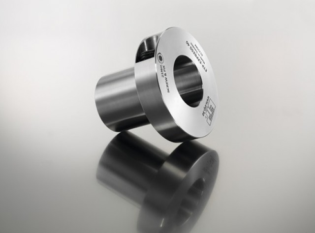
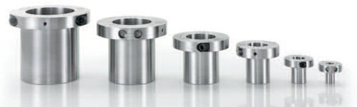
ETP-EXPRESS is available as standard for shafts 15mm -100 mm, with imperial sizes also available. Runout ≤ 0,02 mm. Number of mountings 500 – 2000 (size dependent). The extremely compact design delivers low weight and inertia. ETP-EXPRESS is a hydraulic connection which consists of a double-walled hardened stainless steel sleeve filled with a pressure medium, and a flange. The flange part contains a stainless screw and activating piston with quality seals to maintain pressure.
ETP-EXPRESS is available as standard for shafts 15-100 mm, with imperial sizes also available. Runout ≤ 0,02 mm. Number of mountings 500 – 2000 (size dependent). The extremely thin built-in dimensions allows for a compact design with low weight and inertia.
ETP-EXPRESS is a hydraulic connection which consists of a double-walled hardened stainless steel sleeve filled with a pressure medium, and a flange. The flange part contains a stainless screw and piston with seals to maintain pressure.
When the pressure screw is tightened the double-walled sleeve expands uniformly against shaft and hub and creates a rigid joint. Dismantling is done by loosening the screw. ETP-EXPRESS returns to its original dimensions and can easily be dismantled.
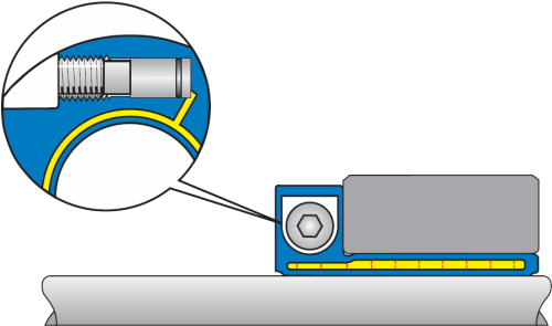
When the pressure screw is tightened to the recommended tightening torque, the piston has reached the bottom of the bore. ETP-EXPRESS R has created a uniform surface pressure against the shaft and hub.
![]()
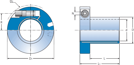
| ETP-EXPRESS® | Dimensions | Transmittable | Screws DIN 915, 12.9 | Polar moment of inertia J kgm2 • 10-3 | Weight kg | ||||||||||
|---|---|---|---|---|---|---|---|---|---|---|---|---|---|---|---|
| torque | axial force | radial force | |||||||||||||
| d mm | D mm | D1 mm | D2* mm | L mm | L1 mm | T Nm | FA kN | FR kN | Dim. | R mm | N mm | Tt Nm | |||
| 15 | 15 | 18 | 46 | 48,9 | 25 | 39 | 46 | 5,1 | 0,5 | M10 | 15,1 | 5 | 5 | 0,04 | 0,16 |
| 5/8" | 15,875 | 19 | 47 | 49,8 | 26 | 40 | 53 | 5,5 | 0,5 | M10 | 15,6 | 5 | 5 | 0,05 | 0,17 |
| 19 | 19 | 23 | 50,5 | 53,0 | 28 | 42 | 85 | 7,3 | 1 | M10 | 17,4 | 5 | 5 | 0,06 | 0,20 |
| 3/4" | 19,05 | 23 | 50,5 | 53,0 | 28 | 42 | 85 | 7,3 | 1 | M10 | 17,4 | 5 | 5 | 0,06 | 0,20 |
| 20 | 20 | 24 | 51,5 | 54,1 | 30 | 44 | 110 | 9,1 | 1 | M10 | 18 | 5 | 5 | 0,07 | 0,21 |
| 22 | 22 | 27 | 55,5 | 60,5 | 32 | 46 | 130 | 9,6 | 1,2 | M10 | 19,3 | 5 | 5 | 0,10 | 0,25 |
| 7/8" | 22,225 | 27 | 55,5 | 60,5 | 32 | 46 | 130 | 9,6 | 1,2 | M10 | 19,3 | 5 | 5 | 0,10 | 0,25 |
| 24 | 24 | 29 | 57,5 | 62,3 | 33 | 47 | 190 | 13 | 1,4 | M10 | 20,3 | 5 | 5 | 0,11 | 0,27 |
| 25 | 25 | 30 | 58 | 62,9 | 35 | 49 | 230 | 15 | 1,5 | M10 | 20,8 | 5 | 5 | 0,12 | 0,27 |
| 1" | 25,4 | 31 | 59 | 63,8 | 35 | 49 | 190 | 12 | 1,5 | M10 | 21,2 | 5 | 5 | 0,13 | 0,29 |
| 28 | 28 | 34 | 63 | 69,6 | 38 | 52 | 280 | 16 | 1,8 | M10 | 22,6 | 5 | 5 | 0,17 | 0,34 |
| 1 1/8" | 28,575 | 35 | 63,5 | 70,1 | 39 | 53 | 290 | 16 | 1,8 | M10 | 23 | 5 | 5 | 0,18 | 0,35 |
| 30 | 30 | 36 | 64,5 | 71,0 | 40 | 54 | 380 | 21 | 2 | M10 | 23,6 | 5 | 5 | 0,19 | 0,35 |
| 1 1/4" | 31,75 | 39 | 68,5 | 77,7 | 42 | 56 | 430 | 22 | 2,2 | M10 | 24,8 | 5 | 5 | 0,25 | 0,42 |
| 32 | 32 | 39 | 68,5 | 77,7 | 42 | 56 | 440 | 22 | 2,2 | M10 | 24,8 | 5 | 5 | 0,25 | 0,42 |
| 1 3/8" | 34,925 | 42 | 73 | 85,1 | 45 | 59 | 640 | 30 | 2,5 | M10 | 26,4 | 5 | 5 | 0,32 | 0,48 |
| 35 | 35 | 42 | 73 | 85,1 | 45 | 59 | 640 | 30 | 2,5 | M10 | 26,4 | 5 | 5 | 0,32 | 0,48 |
| 1 7/16" | 365,125 | 44 | 74,5 | 86,6 | 48 | 62 | 740 | 33 | 2,6 | M10 | 27,3 | 5 | 5 | 0,36 | 0,52 |
| 38 | 38 | 46 | 84,5 | 89,5 | 52 | 72 | 890 | 38 | 2,8 | M16 | 31 | 8 | 21 | 0,76 | 0,84 |
| 1 1/2" | 38,1 | 46 | 84,5 | 89,5 | 52 | 72 | 890 | 38 | 2,8 | M16 | 31 | 8 | 21 | 0,76 | 0,84 |
| 40 | 40 | 48 | 86,5 | 91,2 | 55 | 75 | 1100 | 45 | 3 | M16 | 32 | 8 | 21 | 0,84 | 0,88 |
| 42 | 42 | 51 | 89 | 93,5 | 56 | 76 | 1100 | 43 | 3,2 | M16 | 33,2 | 8 | 21 | 0,97 | 0,96 |
| 1 3/4" | 44,45 | 54 | 93 | 100,3 | 58 | 78 | 1400 | 51 | 3,5 | M16 | 34,8 | 8 | 21 | 1,20 | 1,10 |
| 45 | 45 | 54 | 93 | 100,3 | 58 | 78 | 1400 | 51 | 3,5 | M16 | 34,8 | 8 | 21 | 1,17 | 1,05 |
| 48 | 48 | 59 | 97 | 103,8 | 59 | 79 | 1700 | 57 | 4 | M16 | 36,8 | 8 | 21 | 1,46 | 1,21 |
| 1 15/16" | 492,125 | 60 | 98,5 | 105,1 | 60 | 80 | 1900 | 63 | 4,3 | M16 | 37,5 | 8 | 21 | 1,57 | 1,27 |
| 50 | 50 | 60 | 98,5 | 105,1 | 60 | 80 | 1900 | 63 | 4,5 | M16 | 37,5 | 8 | 21 | 1,52 | 1,20 |
| 2" | 50,8 | 61 | 101,5 | 111,8 | 60 | 80 | 1900 | 62 | 4,5 | M16 | 38 | 8 | 21 | 1,72 | 1,28 |
| 55 | 55 | 67 | 106 | 115,9 | 65 | 85 | 2400 | 71 | 5 | M16 | 40,5 | 8 | 21 | 2,18 | 1,50 |
| 60 | 60 | 73 | 115,5 | 132,7 | 70 | 90 | 3300 | 90 | 5,3 | M16 | 43,3 | 8 | 21 | 3,17 | 1,85 |
| 65 | 65 | 79 | 120,5 | 137 | 75 | 95 | 4400 | 112 | 5,6 | M16 | 46,1 | 8 | 21 | 4,1 | 2,13 |
| 2 1/2" | 63,5 | 77 | 119 | 134.6 | 73 | 93 | 4000 | 105 | 5,4 | M16 | 45,1 | 8 | 21 | 3,74 | 2,04 |
| 70 | 70 | 85 | 135,5 | 153,9 | 85 | 109 | 5600 | 130 | 6,4 | M20 | 50,8 | 10 | 39 | 7,12 | 3,04 |
| 3" | 76,2 | 92 | 141,5 | 157.8 | 91 | 115 | 7500 | 160 | 7 | M20 | 54,1 | 10 | 39 | 9,01 | 3,48 |
| 80 | 80 | 97 | 145,5 | 162,6 | 95 | 119 | 8700 | 180 | 7,5 | M20 | 56,3 | 10 | 39 | 10,35 | 3,75 |
| 90 | 90 | 109 | 155,5 | 171,7 | 105 | 129 | 12000 | 220 | 8,6 | 2 x M20** | 61,8 | 10 | 39 | 15,20 | 4,80 |
| 100 | 100 | 121 | 166 | 181,0 | 115 | 139 | 17000 | 280 | 9,7 | 2 x M20** | 67,3 | 10 | 39 | 21,90 | 5,90 |
| T= Transmittable torque when axial force is 0. | } When the screw is tightened to Tt. | Tt= Recommended tightening torque for the screw/screws. Further tightening does not increase the pressure. * D2 is valid before mounting. ** Pressure screws positioned in the same direction. Dimensions subject to alterations without notice. | |||||||||||||
| FA=Transmittable axial force when torque is 0. | |||||||||||||||
| FR=Max transmittable radial force at continuous operation. Max allowed bending torque: 5% of transmittable torque T. | |||||||||||||||
Shaft h7 for d = 15 mm.
Shaft k6-h7 for d = 19, 22, 24, 28, 32, 38, 42, 48, 55 mm.
Shaft h8 for all other dimensions d.
Hub H7.
Transmittable torque, T, is for static load. If the load is alternating or pulsating torque, reduce the transmittable torque, T, with the following factors: (factor x T).
Alternating: 0,5 x T.
Pulsating: 0,6 x T.