| ETP-CLASSIC® | Dimensions | Transmittable | Screws** DIN 933, A4 | Polar moment of inertia J kgm2 • 10-3 | Weight kg | ||||||||||
|---|---|---|---|---|---|---|---|---|---|---|---|---|---|---|---|
| torque | axial force | radial force | |||||||||||||
| d mm | D mm | D1 mm | D2 mm | L mm | L1* mm | L2* mm | T Nm | FA kN | FR kN | Ant. | Dim. | Tt Nm | |||
| 15 | 15 | 23 | 38 | 28,5 | 17 | 30 | 35 | 55 | 7,3 | 2,5 | 3 | M5 | 6 | 0,019 | 0,10 |
| 19 | 19 | 28 | 45 | 35 | 21 | 37 | 42 | 100 | 10,6 | 5,8 | 3 | M5 | 8 | 0,045 | 0,17 |
| 20 | 20 | 28 | 45 | 35 | 22 | 37 | 42 | 125 | 12,5 | 6,6 | 3 | M5 | 8 | 0,043 | 0,16 |
| 22 | 22 | 32 | 49 | 40 | 22 | 37 | 42 | 135 | 12,3 | 8,2 | 4 | M5 | 8 | 0,063 | 0,20 |
| 24 | 24 | 34 | 49 | 40 | 25 | 40 | 45 | 200 | 16,7 | 9,8 | 4 | M5 | 8 | 0,066 | 0,20 |
| 25 | 25 | 34 | 49 | 40 | 27 | 43 | 48 | 250 | 20,0 | 10,6 | 4 | M5 | 8 | 0,067 | 0,20 |
| 28 | 28 | 39 | 55 | 46 | 29 | 45 | 50 | 300 | 21,4 | 13,1 | 4 | M5 | 8 | 0,112 | 0,27 |
| 30 | 30 | 41 | 57 | 47,5 | 32 | 47 | 52 | 420 | 28,0 | 14,7 | 4 | M5 | 8 | 0,133 | 0,30 |
| 32 | 32 | 43 | 60 | 50,5 | 34 | 52 | 57 | 420 | 26,3 | 16,3 | 4 | M5 | 8 | 0,180 | 0,35 |
| 35 | 35 | 47 | 63 | 53,5 | 37 | 55 | 60 | 650 | 37,1 | 18,8 | 6 | M5 | 8 | 0,230 | 0,41 |
| 38 | 38 | 50 | 65 | 56 | 41 | 59 | 64 | 750 | 39,5 | 21,2 | 6 | M5 | 8 | 0,277 | 0,44 |
| 40 | 40 | 53 | 70 | 60,5 | 43 | 63 | 68 | 940 | 47,0 | 22,8 | 6 | M5 | 8 | 0,408 | 0,57 |
| 42 | 42 | 55 | 70 | 60,5 | 45 | 65 | 70 | 940 | 44,8 | 24,4 | 6 | M5 | 8 | 0,414 | 0,56 |
| 45 | 45 | 59 | 77 | 66,5 | 49 | 69 | 75 | 1290 | 57,3 | 26,9 | 6 | M6 | 13 | 0,636 | 0,73 |
| 48 | 48 | 62 | 80 | 69,5 | 52 | 73 | 79 | 1570 | 65,4 | 29,3 | 6 | M6 | 13 | 0,761 | 0,80 |
| 50 | 50 | 65 | 83 | 72,5 | 53 | 76 | 82 | 1900 | 76,0 | 30,9 | 6 | M6 | 13 | 0,943 | 0,91 |
| 55 | 55 | 71 | 88 | 78 | 58 | 82 | 88 | 2500 | 90,9 | 35,0 | 8 | M6 | 13 | 1,301 | 1,09 |
| 60 | 60 | 77 | 95 | 84,5 | 64 | 90 | 96 | 3400 | 113 | 39,1 | 8 | M6 | 13 | 1,959 | 1,40 |
| 65 | 65 | 84 | 102 | 91 | 68 | 96 | 102 | 3500 | 108 | 43,1 | 8 | M6 | 13 | 2,780 | 1,72 |
| 70 | 70 | 90 | 113 | 99 | 72 | 99 | 107 | 5200 | 149 | 47,2 | 6 | M8 | 32 | 4,035 | 2,09 |
| 75 | 75 | 95 | 118 | 104 | 85 | 114 | 122 | 6300 | 168 | 51,3 | 6 | M8 | 32 | 5,500 | 2,51 |
| 80 | 80 | 100 | 123 | 109 | 90 | 120 | 128 | 8800 | 220 | 55,0 | 6 | M8 | 32 | 8,100 | 2,68 |
| 85 | 85 | 106 | 129 | 115 | 95 | 125 | 133 | 8800 | 207 | 58,0 | 6 | M8 | 32 | 9,500 | 3,09 |
| 90 | 90 | 112 | 135 | 121 | 100 | 133 | 141 | 11000 | 244 | 60,0 | 8 | M8 | 32 | 12,200 | 3,52 |
| 95 | 95 | 120 | 143 | 129 | 105 | 139 | 147 | 12800 | 269 | 61,5 | 8 | M8 | 32 | 17,100 | 4,46 |
| 100 | 100 | 125 | 148 | 134 | 110 | 145 | 153 | 15500 | 310 | 62,0 | 8 | M8 | 32 | 19,950 | 4,87 |
| T= Transmittable torque when axial force is 0. | } When the screw is tightened to Tt. | Tt= Recommended tightening torque for the screws. * The dimensions are valid before mounting. Dimensions subject to alterations without notice. | |||||||||||||
| FA=Transmittable axial force when torque is 0. | |||||||||||||||
| FR=Max transmittable radial force at continuous operation. Max allowed bending torque: 15% of transmittable torque T. | |||||||||||||||
Shaft h8 – k6 (size 15 only h7)
When using k6 shaft – transmittable torque will increase by 20%.
Can also be used with h9 shaft – Transmittable torque will be
reduced by 25%.
Hub H7.
Transmittable torque, T, is for static load.
If the load is alternating or pulsating torque, reduce
the transmittable torque, T, with the following factors:
(factor x T).
Alternating:
0,6 x T for sizes 15 – 30 mm.
0,5 x T for sizes 32 – 100 mm.
Pulsating:
0,7 x T for sizes 15 – 30 mm.
0,6 x T for sizes 32 – 100 mm.
By increasing the tightening torque of the screw sizes
according to the table, the transmittable torque can
be increased by 25%.
Note: Only to be used when operating temperature
≤ mounting temperature.
Max. tightening torque (screw quality 12.9)
| M5 | M6 | M8 |
|---|---|---|
| 10 Nm | 17 NM | 40 Nm |
| ETP-CLASSIC® | Dimensions | Transmittable | Screws** DIN 912, 12.9 | ||||||||
|---|---|---|---|---|---|---|---|---|---|---|---|
| torque | axial force | ||||||||||
| d mm | D mm | D1 mm | L mm | L1* mm | L2* mm | T Nm | FA kN | No. | Dim. | Tt Nm | |
| 3/4 " | 3/4 " | 28 | 45 | 21 | 35 | 40 | 88 | 9,3 | 3 | M5 | 8 |
| 7/8 " | 7/8 " | 32 | 49 | 22 | 37 | 42 | 135 | 12,1 | 4 | M5 | 8 |
| 15/16 " | 15/16 " | 34 | 49 | 25 | 39 | 44 | 175 | 14,7 | 4 | M5 | 8 |
| 1 " | 1" | 35 | 51 | 27 | 41 | 46 | 195 | 16,2 | 4 | M5 | 8 |
| 1 1/8 " | 1 1/8 " | 39 | 55 | 29 | 43 | 48 | 280 | 19,5 | 4 | M5 | 8 |
| 1 3/16 " | 1 3/16 " | 41 | 57 | 32 | 47 | 52 | 340 | 22,5 | 4 | M5 | 8 |
| 1 1/4 " | 1 1/4 " | 43 | 60 | 34 | 50 | 55 | 410 | 26,1 | 4 | M6 | 13 |
| 1 3/8 " | 1 3/8 " | 47 | 63 | 37 | 53 | 58 | 540 | 31,1 | 6 | M5 | 8 |
| 1 7/16 " | 1 7/16 " | 50 | 65 | 37 | 54 | 59 | 580 | 31,8 | 6 | M5 | 8 |
| 1 1/2 " | 1 1/2 " | 52 | 68 | 41 | 57 | 62 | 700 | 36,7 | 6 | M5 | 8 |
| 1 5/8 " | 1 5/8 " | 55 | 70 | 44 | 63 | 68 | 850 | 41,2 | 6 | M5 | 8 |
| 1 3/4 " | 1 3/4 " | 59 | 77 | 49 | 67 | 73 | 1180 | 53,0 | 6 | M6 | 13 |
| 1 15/16 " | 1 15/16 " | 65 | 83 | 52 | 74 | 80 | 1450 | 58,9 | 6 | M6 | 13 |
| 2 " | 2 " | 68 | 88 | 53 | 74 | 80 | 1620 | 64,3 | 6 | M6 | 13 |
| 2 7/16 " | 2 7/16 " | 81 | 99 | 60 | 85 | 91 | 2800 | 90,5 | 8 | M6 | 13 |
| 2 1/2 " | 2 1/2 " | 84 | 107 | 62 | 86 | 94 | 3100 | 97,6 | 6 | M8 | 32 |
| 2 15/16 " | 2 15/16 " | 95 | 118 | 85 | 108 | 116 | 5300 | 153,0 | 6 | M8 | 32 |
| 3 " | 3 " | 98 | 121 | 74 | 101 | 109 | 5300 | 139,1 | 6 | M8 | 32 |
| 4 " | 4 " | 130 | 155 | 97 | 128 | 136 | 12500 | 264,0 | 8 | M8 | 32 |
| T= Transmittable torque when axial force is 0. | } When the screw is tightened to Tt. | Tt= Recommended tightening torque for the screws. * The dimensions are valid before mounting. Dimensions subject to alterations without notice. | |||||||||
| FA=Transmittable axial force when torque is 0. | |||||||||||
| Max allowed bending torque: 15% of transmittable torque T. | |||||||||||
ETP-CLASSIC is also available in a large assortment of inch sizes. The main dimensions are given in the table, for more information please refer to technical data for ETP-CLASSIC.
| ETP-CLASSIC | Shaft tolerance |
|---|---|
| 3/4" | 0 to –0,0015" |
| 7/8" π 1 1/2" | 0 to –0,0020" |
| 1 5/8" π 2 15/16" | 0 to –0,0030" |
| 3" | 0 to –0,0040" |
| 4" | 0 to –0,0030" |
| ETP-CLASSIC | Hub tolerance |
|---|---|
| 3/4" -1 15/16" | 0 to +0,0010" |
| 2" π 2 7/16" | 0 to +0,0012" |
| 2 1/2" π 4" | 0 to +0,0014" |
| ETP-CLASSIC® | Dimensions | Transmittable | Screws** DIN 912, 12.9 | Weight kg | ||||||||
|---|---|---|---|---|---|---|---|---|---|---|---|---|
| torque | axial force | |||||||||||
| d mm | D mm | D1 mm | L mm | L1* mm | L2* mm | T Nm | FA kN | No. | Dim. | Tt Nm | ||
| S-19 | 19 | 28 | 45 | 13 | 26 | 31 | 53 | 5 | 3 | M5 | 8 | 0,15 |
| S-20 | 20 | 28 | 45 | 15 | 28 | 33 | 75 6 | 6 | 3 | M5 | 8 | 0,14 |
| S-25 | 25 | 34 | 49 | 15 | 29 | 34 | 120 10 | 10 | 4 | M5 | 8 | 0,17 |
| S-30 | 30 | 41 | 57 | 20 | 34 | 39 | 210 14 | 14 | 4 | M5 | 8 | 0,24 |
| S-35 | 35 | 47 | 63 | 22 | 38 | 43 | 330 19 | 19 | 6 | M5 | 8 | 0,32 |
| S-40 | 40 | 53 | 70 | 25 | 42 | 47 | 500 26 | 26 | 6 | M5 | 8 | 0,46 |
| S-45 | 45 | 59 | 77 | 28 | 45 | 51 | 700 31 | 31 | 6 | M6 | 13 | 0,57 |
| S-50 | 50 | 65 | 83 | 26 | 45 | 51 | 1000 40 | 40 | 6 | M6 | 13 | 0,72 |
| T= Transmittable torque when axial force is 0. | } When the screw is tightened to Tt. | Tt= Recommended tightening torque for the screws. * The dimensions are valid before mounting. Dimensions subject to alterations without notice. | ||||||||||
| FA=Transmittable axial force when torque is 0. | ||||||||||||
| Max allowed bending torque: 15% of transmittable torque T. | ||||||||||||
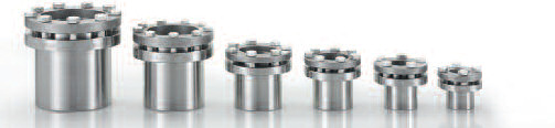
ETP-CLASSIC is also available in a shorter version, type S, which is especially suitable for small hubs.The main dimensions are given in the table, for more information please refer to technical data for ETP-CLASSIC.
Shaft: h9 (for size 19: k6-h8).
Hub: H7.
![]()
| ETP-CLASSIC® | Dimensions | Transmittable | Screws** DIN 933, A4 | Polar moment of inertia J kgm2 • 10-3 | Weight kg | ||||||||||
|---|---|---|---|---|---|---|---|---|---|---|---|---|---|---|---|
| torque | axial force | radial force | |||||||||||||
| d mm | D mm | D1 mm | D2 mm | L mm | L1* mm | L2* mm | T Nm | FA kN | FR kN | Ant. | Dim. | Tt Nm | |||
| R-15 | 15 | 23 | 38 | 28,5 | 17 | 30 | 34 | 45 | 6,0 | 2,5 | 4 | M5 | 4,5 | 0,019 | 0,10 |
| R-20 | 20 | 28 | 45 | 35 | 22 | 37 | 41 | 100 | 10,0 | 6,6 | 5 | M5 | 4,5 | 0,044 | 0,16 |
| R-25 | 25 | 34 | 49 | 40 | 27 | 43 | 47 | 210 | 16,8 | 10,6 | 7 | M5 | 4,5 | 0,070 | 0,21 |
| R-30 | 30 | 41 | 57 | 47,5 | 32 | 47 | 51 | 350 | 23,3 | 14,7 | 7 | M5 | 4,5 | 0,137 | 0,30 |
| R-35 | 35 | 47 | 63 | 53,5 | 37 | 55 | 59 | 500 | 28,5 | 18,8 | 9 | M5 | 4,5 | 0,234 | 0,41 |
| R-40 | 40 | 53 | 70 | 60,5 | 43 | 63 | 67 | 750 | 37,5 | 22,8 | 9 | M5 | 4,5 | 0,414 | 0,58 |
| R-45 | 45 | 59 | 77 | 66,5 | 49 | 69 | 73 | 1100 | 48,8 | 26,9 | 9 | M6 | 7,8 | 0,647 | 0,74 |
| R-50 | 50 | 65 | 83 | 72,5 | 53 | 76 | 80 | 1550 | 62,0 | 30,9 | 9 | M6 | 7,8 | 0,957 | 0,92 |
| T= Transmittable torque when axial force is 0. | } When the screw is tightened to Tt. | Tt= Recommended tightening torque for the screws. * The dimensions are valid before mounting. Dimensions subject to alterations without notice. | |||||||||||||
| FA=Transmittable axial force when torque is 0. | |||||||||||||||
| FR=Max transmittable radial force at continuous operation. Max allowed bending torque: 15% of transmittable torque T. | |||||||||||||||